Sources -15, Figure 4-6 – National Instruments 6023E User Manual
Page 45
Chapter 4
Signal Connections
© National Instruments Corporation
4-15
Differential Connections for Nonreferenced or
Floating Signal Sources
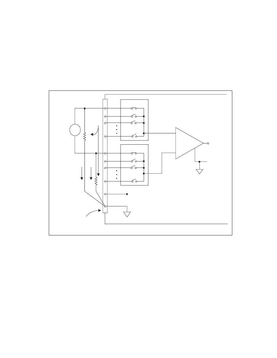
Figure 4-6 shows how to connect a floating signal source to a channel
configured in DIFF input mode.
Figure 4-6. Differential Input Connections for Nonreferenced Signals
Figure 4-6 shows two bias resistors connected in parallel with the signal
leads of a floating signal source. If you do not use the resistors and the
source is truly floating, the source is not likely to remain within the
common-mode signal range of the PGIA. The PGIA then saturates, causing
erroneous readings.
+
–
+
Floating
Signal
Source
Input Multiplexers
V
m
Measured
Voltage
–
–
+
I/O Connector
AIGND
Bias
Current
Return
Paths
Bias
resistors
(see text)
ACH–
ACH+
AISENSE
Selected Channel in DIFF Configuration
PGIA
Programmable Gain
Instrumentation
Amplifier
Vs