Sequencing increases monitoring efficiency, User management protects against misuse, Tour sequence – Panasonic WJ-SX150A User Manual
Page 3: Group sequence, Video signal, Control data, Synchronous signals (vd2), Alarm signals, Rs-485 port, Rs232c external serial interface
B/W Cameras
WV-BP330 Series, WV-BP140 Series
Color Cameras
WV-CW474A Series, WV-CW244 Series, WV-CF224,
WV-CF212, WV-CW374, WV-CL920A Series,
WV-CP480 Series, WV-CP254H, WV-CP240 Series
Integrated Dome Cameras
WV-CW864A, WV-CS954, WV-CS574
RS-485 Port
Up to 64 cameras can be controlled through the built-in RS-485 ports.
RS232C External Serial Interface
The RS232C port permits system set-up and alarm history
management from a personal computer. It also supports time-lapse VCR
and other peripherals.
User Management Protects Against Misuse
OPE
7
OPE
8
OPE
9
OPE
10
OPE
11
OPE
12
OPE
13
OPE
14
OPE
15
OPE
16
Level 3
Level 2
Level 1
Priority
OPERATOR’S LEVEL TABLE
31256
34397
32356
34682
34645
31625
OPE
2
OPE
3
OPE
4
OPE
5
OPE
6
Password
21233
OPE
1
12123
25376
21325
22342
24953
39262
39768
37322
31828
SX150 Setup
Camera Setup
Indicate Alarm History
Indicate Video Loss History
Indicate System Status
One Alarm Reset
All Alarm Reset
Camera Cleaning
Select Camera
Start Sequence
Register Preset
Display OSD
Control Camera
Control Recorder
Indicate System Status
One Alarm Reset
All Alarm Reset
Camera Cleaning
Select Camera
Start Sequence
Register Preset
Display OSD
Control Camera
Control Recorder
Display OSD
Control Camera
Control Recorder
Pre-set the sequence in which to view an image from a series of different cameras. The WV-CU650 System Controller
makes it possible to choose from a variety of sequence patterns with push-button ease. Just select the one that provides
the most effective coverage.
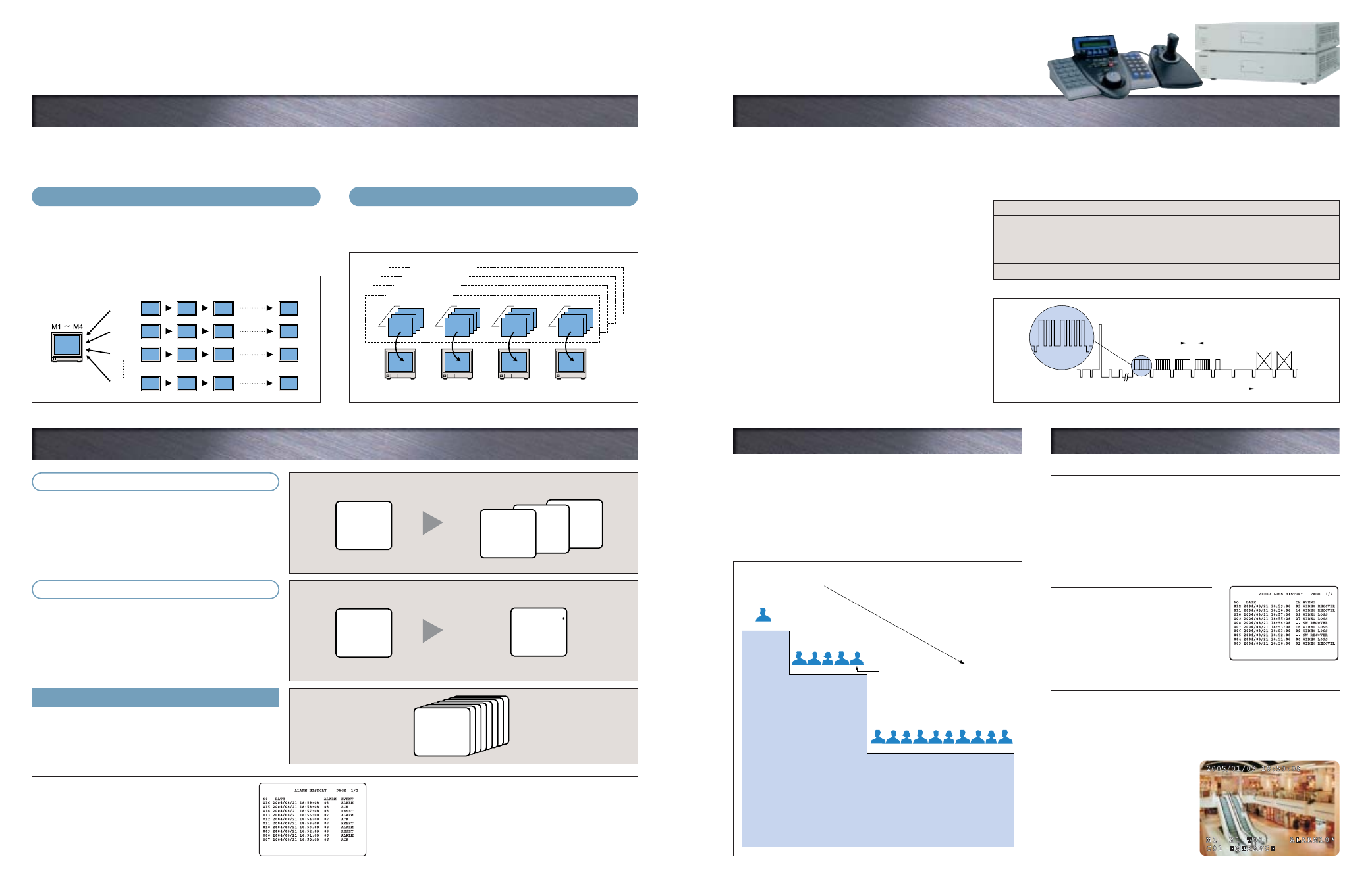
Tour Sequence
The monitor switches automatically, following a pre-set sequence from
channel 1 to channel 64. Each sequence can include up to 64 steps,
with each step set from one to 30 seconds in length. In addition, dome
cameras can also be pre-set to precisely the viewing angle you need.
Up to 32 touring patterns can be stored in memory for easy recall.
step 1
Tour 1
C1
Tour 2
C5
Tour 3
C9
Tour 32
C13
step 2
C2
C6
C10
C14
step 3
C3
C7
C11
C15
step 64
C16
C4
C8
C12
The image shifts automatically from one camera to another, as programmed.
The images can
be seen on any
monitor.
Group Sequence
(Simultaneous tour sequencing)
Sequence mode
(In response to spot alarm)
This feature allows you to activate multiple, pre-set tour sequences by
pushing a single button. Each group can include up to four tour
sequences. Up to four group sequences can be stored in memory.
1. Video signal
Transmits the image captured by the camera to the
Matrix Switcher.
2. Control data
Transmits settings from the Matrix Switcher to the camera.
Allows control of pan, tilt and zoom features of WV-CW864A/
WV-CS954/WV-CS574 intelligent dome cameras, and via
WV-RC100/WV-RC150 remote control receivers,
WV-CL920A/WV-CP480/WV-CP240 Series.
3. Synchronous signals (VD2)
Supports almost all Panasonic CCD cameras (see compatible
camera list). Allows simultaneous image switching by
cameras and the Matrix Switcher, preventing image distortion.
4. Alarm signals
Transmits alarm signals received from the camera to the
Matrix Switcher, initiating the pre-set alarm event sequence.
When the alarm signal is received, the monitor and camera
instantly switch to the spot from which it originates. When two
or more alarms are received, the system switches instantly to
the spot from which the latest alarm originates. Pressing the
ACK key switches operator control to the camera from which
the alarm was received.
Camera 1 shows spot where alarm originated.
Image shifts from Camera 8 to Camera 1.
Group sequence 1
Monitor 1
Tour 1
C1
Monitor 2
Tour 5
C20
Monitor 3
Tour 2
C5
Monitor 4
Tour 7
C15
Group sequence 2
Group sequence 3
Group sequence 4
This system manages user names and other user information for
up to 16 users, who may use the controller itself or log in from a
personal computer. Matrix System150 operation can be limited
by use of five user attributes including operator number,
password, level, priority, and the cameras the user is permitted
to operate. This user management feature prevents improper
use by outsiders or unauthorized persons.
Operator Registration
Monitor 1: Alarm 1 received
from Camera 1.
Monitor1: Alarms are received sequentially
from Alarm 1 (Camera 1) to Alarm 8 (Camera 8).
Video Loss Detection automatically
senses camera malfunction
This feature automatically senses loss
of video signal input and displays a
warning on the monitor, allowing speedy
response to such problems as power
outage, severed camera cables or
damaged cameras.
Monitor Character Displays
Four types of information are displayed on the monitor using the built-in
character generator IC.
1. Date and time
Choice of five date styles and 24-hour or 12-hour time displays.
2. Camera title
A label up to 20 characters long can
be added to the camera number.
3. Monitor status
Shows monitor number, keyboard
number, and sequence status.
4. Event information
Shows time and other information
concerning alarm or timed events.
Sequencing Increases Monitoring Efficiency
User Management Protects Against Misuse
Other Convenient Features
Other Convenient Features
Timing Pulse (VD2) for Vertical Genlock
Camera to Matrix Switcher
Matrix Switcher to Camera
Data 8-bit x 4
Alarm
Video
Vertical Blanking
Since 1988, most of Panasonic cameras have been designed and manufactured to accept VD2 signal for system integration.
VD2 Compatible Panasonic Camera List
Concerning start of Sequence Alarm
The system can also be pre-set to start a tour sequence when
an alarm signal is received. However, once a sequence
begins, a second alarm cannot enter the monitor, as it can in
sequence or hold mode.
Most recent 100 alarms display
The monitor display shows up to 100 of the most recent
alarms in chronological order, allowing quick
confirmation of alarm location, date, and time. Images
can be recalled and reviewed with push button ease
using the WV-CU650 system controller.
Alarm history management using
a personal computer
The alarm log can be output to a personal computer using
the RS232C serial port, allowing use of the personal
computer to manage alarm histories.
CH 1
ALARM 01
CH 8
ALARM 08
CH 5
ALARM 05
CH 1
ALARM 01
Hold mode
(In response to spot alarm)
When the alarm signal is received, the monitor shows the
image from the pre-set camera. When two or more alarms are
received, the monitor continues to show the image of the spot
from which the first alarm was received. Pressing the ACK key
switches operator control to the camera from which the alarm
was received.
Camera 1 shows spot where alarm originated.
Only the image from Camera 1 is seen. The * signal that appears
on the monitor indicates that additional alarms have been received.
Monitor 1: Alarm 1 received
from Camera 1.
Monitor1: Alarms are received sequentially
from Alarm 1 (Camera 1) to Alarm 8 (Camera 8).
CH 1
ALARM 01
Tour Sequence 1 starts automatically.
Monitor 1: Alarm 1
(Tour Sequence 1)
CH 1
ALARM 01
T-SEQ 1
ALARM 01
Sequencing and Alarm. Just Two of Many Features that Support Effective Surveillance.
Sequencing Increases Monitoring Efficiency
Video signals, control data, synchronous signals (VD2), and alarm signals are all transmitted over the same coaxial,
multiplex cable. Use of the same cable reduces both time and trouble required for camera installation. Each coaxial cable
can be up to 900 m (3,000 feet) long.
64 Channels are All Transmitted via the Same Coaxial Cable
64 Channels are All Transmitted via the Same Coaxial Cable
Instant No-Escape Alarms
Instant No-Escape Alarms
Video Loss History Table
The above all photographs were taken for the purpose of explanation; actual images may differ.
Example of Character Displays
WV-CU650
WJ-SX150A
4
5