Pride Mobility Jazzy 1170XL User Manual
Page 26
26
www.pridemobility.com
Jazzy 1170XL
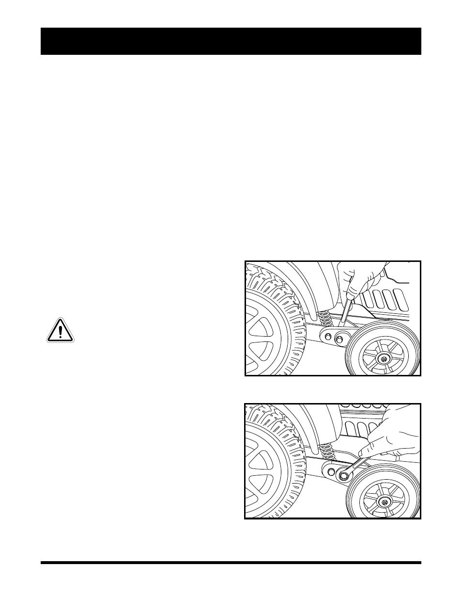
Figure 24. Anti-Tip Bracket (Inner Locknut)
Figure 25. Anti-Tip Wheel Adjustment (Cam)
V . C O M F O R T A D J U S T M E N T S
To adjust the ELR length:
1. Remove the two adjustment screws from the side of each leg rest extension. See figure 23.
2. Slide the leg rest up or down to the desired length.
3. Reinstall the two adjustment screws.
To adjust the ELR angle:
1. Push down release lever B. See figure 23.
2. Move the leg rest to the desired angle.
Anti-tip Wheels
The anti-tip wheels are designed to give your power chair increased stability on rough surfaces. The anti-tip
wheels are preset for smooth surfaces or indoor use only. If you plan on using your power chair on rough
surfaces, it may be necessary to adjust the anti-tip wheels to better suit your needs. The anti-tip wheels may
need adjustment if either of the following occur:
n When coming to a stop, your power chair tips forward excessively.
n The anti-tip wheels constantly rub the ground.
WARNING! Consult your authorized
Pride Provider before attempting to
change the anti-tip wheel height!
Changing the anti-tip wheel height
affects handling under deceleration!
WARNING! The higher you raise the
anti-tip wheels, the more you increase
your power chairs tendency to tilt
forward when coming to a stop. You
can compensate for this by having
your authorized Pride Provider make
a small adjustment to the pre-
programmed deceleration setting in
the controller or by moving the seat
assembly farther to the rear of your
power chair.
To adjust the anti-tip wheels:
1. Place a wrench on the inner locknut of the anti-
tip bracket located right after the shock strut. See
figure 24.
2. Turn the locknut counterclockwise to loosen the
cam.
3. Place your wrench on the adjustable cam located
on the other side of the locknut.
4. To adjust the anti-tip upward, turn the cam coun-
terclockwise. To adjust the anti-tip downward, turn
the cam clockwise. See figure 25.
5. Tighten the locknut.
NOTE: Each drive tire must have 35 psi in order for the anti-tip wheels to be properly adjusted.