Panasonic TN Relay User Manual
Page 4
TN
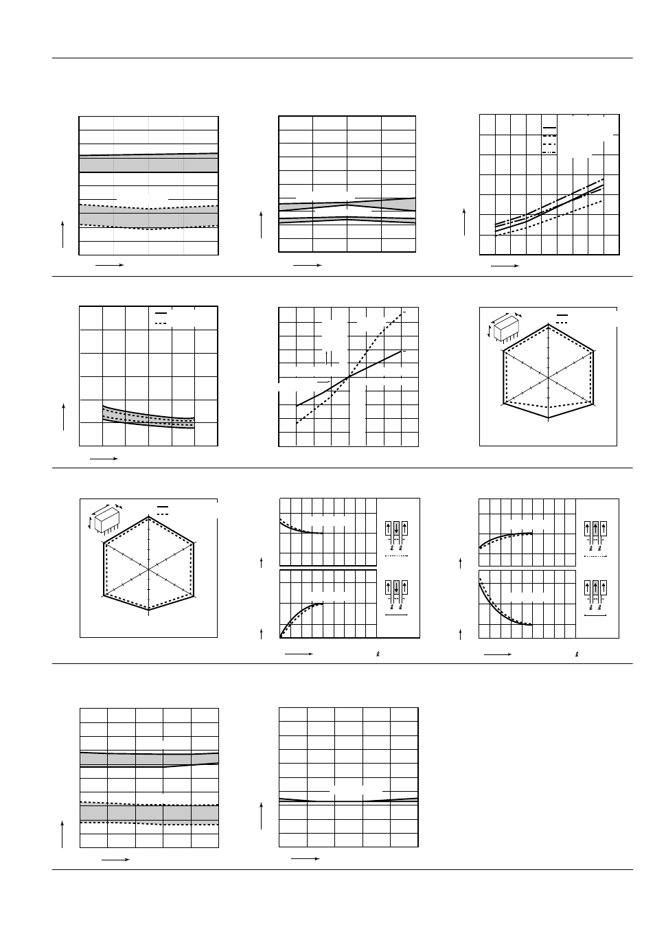
4. Electrical life (DC load)
Tested sample: TN2-12V, 10 pcs.
Condition: 1 A 30 V DC resistive load, 20 cpm
Change of pick-up and drop-out voltage
Change of contact resistance
5. Coil temperature rise
Tested sample: TN2-12V
Point measured: Inside the coil
Ambient temperature: Room temperature (25
° to
26
°C), 70°C
(77
° to 79°F), 158°F
Max.
Max.
Min.
Min.
No. of operations,
×10
4
0
10
20
30
40
50
60
70
80
90
100
5
10
15
20
Ratio against the rated voltage %V
Pick-up voltage
Drop-out voltage
5
10
15
20
No.of operations,
×10
4
Contact resistance,m
Ω
0
10
20
30
40
50
60
70
80
90
100
Terminal No.2–3–4
Terminal No.7–8–9
0
Coil applied voltage, %V
Temperature rise,
°C
80
90
100 110 120 130 140 150
10
20
30
40
50
60
70
Carrying current
0 A (Room temp.)
1 A (Room temp.)
0 A (70
°C)
1 A (70
°C)
6. Set/reset time characteristics
Tested sample: TN2-L2-12V, 5 pcs.
7. Ambient temperature characteristics
Tested sample: TN2-12V, 5 pcs.
8-(1). Malfunctional shock (single side stable)
Tested sample: TN2-12V, 6 pcs.
Max.
Min.
0
1
2
3
4
5
6
80
90
100
110
120
Coil applied voltage, %V
Set and reset time, ms
Set time
Reset time
20
0
x
x
Pick-up voltage
40
60
80
–10
–20
–40
10
20
30
40
Drop-out
voltage
Ambient
temperature,
°C
–10
–20
–30
–40
Variation
ratio, %
Y
Z
,
Z
X
,
X
,
X
X
Z
Z
,
Y
Y ,
980m/s
2
980m/s
2
980m/s
2
980m/s
2
980m/s
2
980m/s
2
Y
,
Deenergized condition
Energized condition
8-(2). Malfunctional shock (latching)
Tested sample: TN2-L2-12V, 6 pcs.
9-(1). Influence of adjacent mounting
9-(2). Influence of adjacent mounting
Y
Z
,
Z
X
,
X
,
X
X
Z
Z
,
Y
Y ,
980m/s
2
980m/s
2
980m/s
2
980m/s
2
980m/s
2
980m/s
2
Y
,
Deenergized condition
Energized condition
ON
ON
ON
OFF
OFF
OFF
Inter-relay distance , mm
inch
Rate of change, %
Rate of change, %
0
5
.197
–10
10
0
–10
0
10
Pick-up voltage
Drop-out voltage
ON
ON
ON
OFF
OFF
OFF
Inter-relay distance , mm
inch
Rate of change, %
Rate of change, %
0
5
.197
0
20
10
–10
0
10
Pick-up voltage
Drop-out voltage
10. Actual load test (35 mA 48 V DC wire spring relay load)
Tested sample: TN2-12V, 5 pcs.
Change of pick-up and drop-out voltage
Change of contact resistance
No. of operations,
×10
4
Ratio against the rated voltage, %V
Max.
Min.
Max.
Min.
0
10
10
20
30
40
50
60
70
80
90
100
20
30
40
50
Pick-up voltage
Drop-out voltage
No. of operations,
×10
4
Max.
Min.
0
10
10
20
30
40
50
60
70
80
90
100
20
30
40
50
Contact resistance, m
Ω
Terminal No. 2–3
All Rights Reserved © COPYRIGHT Matsushita Electric Works, Ltd.