Reference data – Panasonic TN Relay User Manual
Page 3
TN
3) 2 coil latching
*Pulse drive (JIS C 5442-1986)
2. Specifications
Notes: *1 This value can change due to the switching frequency, environmental conditions, and desired reliability level, therefore it is recommended to check this with the
actual load. (SX relays are available for low level load switching [10V DC, 10mA max. level])
*2 Refer to 6. Conditions for operation, transport and storage mentioned in AMBIENT ENVIRONMENT.
REFERENCE DATA
Nominal coil
voltage
Set voltage
(at 20
°C
68
°F
)
Reset voltage
(at 20
°C
68
°F
)
Nominal operating
current
[
±10%] (at 20°C
68
°F
)
Coil resistance
[
±10%] (at 20°C
68
°F
)
Nominal operating
power
Max. allowable voltage
(at 20
°C
68
°F
)
Set coil
Reset coil
Set coil
Reset coil
Set coil
Reset coil
3V DC
75%V or less of
nominal voltage*
(Initial)
75%V or less of
nominal voltage*
(Initial)
66.7mA
66.7mA
45
Ω
45
Ω
200mW
200mW
150%V of
nominal voltage
4.5V DC
44.4mA
44.4mA
101.2
Ω
101.2
Ω
5V DC
40mA
40mA
125
Ω
125
Ω
6V DC
33.3mA
33.3mA
180
Ω
180
Ω
9V DC
22.2mA
22.2mA
405
Ω
405
Ω
12V DC
16.7mA
16.7mA
720
Ω
720
Ω
24V DC
12.5mA
12.5mA
1,920
Ω
1,920
Ω
300mW
300mW
120%V of
nominal voltage
Characteristics
Item
Specifications
Contact
Arrangement
2 Form C
Initial contact resistance, max.
Max. 60 m
Ω (By voltage drop 6 V DC 1A)
Contact material
Ag+Au clad
Rating
Nominal switching capacity (resistive load)
1 A 30 V DC, 0.5 A 125 V AC
Max. switching power (resistive load)
30 W (DC), 62.5 VA (AC)
Max. switching voltage
110 V DC,125 V AC
Max. switching current
1 A
Min. switching capacity (Reference value)*
1
10
µA 10mV DC
Nominal operating
power
Single side stable
140 mW (3 to 12 V DC), 200 mW (24 V DC), 300 mW (48 V DC)
1 coil latching
100 mW (3 to 12 V DC), 150 mW (24 V DC)
2 coil latching
200 mW (3 to 12 V DC), 300 mW (24 V DC)
Electrical
characteristics
Insulation resistance (Initial)
Min. 1,000M
Ω (at 500V DC)
Measurement at same location as “Initial breakdown voltage” section.
Breakdown voltage
(Initial)
Between open contacts
750 Vrms for 1 min. (Detection current: 10 mA)
Between contact and coil
1,000 Vrms for 1 min. (Detection current: 10 mA)
Between contact sets
1,000 Vrms for 1 min. (Detection current: 10 mA)
Surge breakdown
voltage (Initial)
Between open contacts
1,500 V (10
×160µs) (FCC Part 68)
Temperature rise (at 20
°C
68
°F
)
Max. 50
°C
(By resistive method, nominal voltage applied to the coil; contact carrying current: 1A.)
Operate time [Set time] (at 20
°C
68
°F
)
Max. 3 ms [Max. 3 ms] (Nominal voltage applied to the coil, excluding contact bounce time.)
Release time [Reset time] (at 20
°C
68
°F
)
Max. 3 ms [Max. 3 ms] (Nominal voltage applied to the coil, excluding contact bounce time.)
(without diode)
Mechanical
characteristics
Shock resistance
Functional
Min. 490 m/s
2
(Half-wave pulse of sine wave: 11 ms; detection time: 10
µs.)
Destructive
Min. 980 m/s
2
(Half-wave pulse of sine wave: 6 ms.)
Vibration resistance
Functional
10 to 55 Hz at double amplitude of 3 mm (Detection time: 10
µs.)
Destructive
10 to 55 Hz at double amplitude of 5 mm
Expected life
Mechanical
Min. 10
8
(at 180 cpm)
Electrical
Min. 2
×10
5
(1 A 30 V DC resistive), Min. 10
5
(0.5 A 125 V AC resistive) (at 20 cpm)
Conditions
Conditions for operation, transport and storage*
2
Ambient temperature: –40
°C to 70°C
–40
°F to 158°F
;
Humidity: 5 to 85% R.H. (Not freezing and condensing at low temperature)
Max. operating speed (at rated load)
20 cpm
Unit weight
Approx. 1.5 g
.053 oz
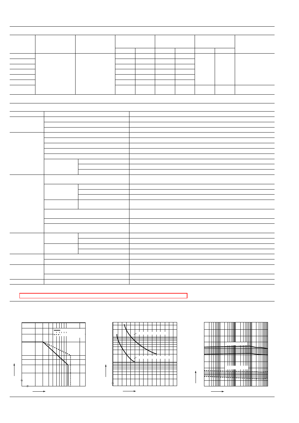
1. Maximum switching capacity
2. Life curve
3. Mechanical life
Tested sample: TN2-12V, 10 pcs.
30
100
200
1.0
0.5
0.4
0.3
0.2
Switching voltage,V
Switching current, A
DC load (cos
ϕ=1)
AC load (cos
ϕ=1)
100
10
0
0.5
1.0
Switching current, A
No. of operations,
×
10
4
125 V AC resistive load
30 V DC resistive load
10
100
1,000
10,000
0
10
20
30
40
50
60
70
80
90
100
Ratio against the rated voltage, %V
No. of operations,
×10
4
Max.
Max.
Min.
Min.
Pick-up voltage
Drop-out voltage
All Rights Reserved © COPYRIGHT Matsushita Electric Works, Ltd.