Paradise P300 User Manual
Page 171
P300H
P300 Series Modem Installation and Operating Handbook
Page 171
P1440 IN G.703 MODE
If the G.703 option is fitted to the P300 Series modem, then G.703 becomes a front panel / software
selectable interface in addition to the standard RS422, V.35 and RS232 interfaces. If G.703 is selected
under
Change
,
Terr-Intfc
,
Electrical
then the following interface description applies.
Note on E1 G.703 cards you must set switch 2 on the G.703 option to select either 75
S
G.703 (on the BNC
connectors) or 120
S
G.703 (on the D type connectors). For the T1 card, or for the E1 card if the impedance
switch is set for 120
S
, then the following pinout applies. Note that although there are both 25 pin EIA530
pinout and 37 pin RS449 pinout connectors on the rear panel, these are simply connected in parallel. Do
not use both connectors at the same time.
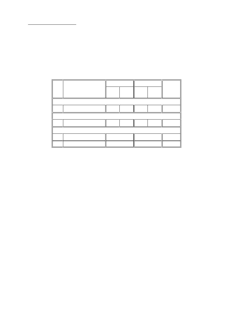
Min
Electrical
Req
Levels
Signal Description
25 pin
37 pin
A
B
A
B
`Tip`
`Ring`
`Tip`
`Ring`
DATA CIRCUIT TOWARDS MODEM (TX)
U
Data In
2
14
4
22
G.703
DATA CIRCUIT FROM MODEM (RX)
U
Data Out
3
16
6
24
G.703
COMMON LINES
Signal Ground
7
19, 20, 21
Ground
U
Shield/Protective ground
1
1
Screen
Line Code / Line Length
For both T1 and E1 G.703 cards the line code is set from the front panel after the electrical interface is
selected. For T1 either AMI or B8ZS is available, for E1 cards AMI or HDB3. In coded (ie non AMI modes)
the modem will display a `Data Marginal` warning whenever a line code violation is detected. For T1 cards
a choice of line lengths is also given to allow the card to pre-compensate the T1 signal for line losses. If
you are in doubt, select the <133 feet option (no pre-compensation).
Switch/Link Settings
For T1 G.703 cards set SW2 to Position 2.
For E1 G.703 cards, SW2 selects either 75
S
G.703 on the BNC connectors or 120
S
G.703 on the D type
connectors
Sw2 position 1
75
S
(via BNC connectors)
Sw2 position 2
120
S
(via either D type connector) or T1 G.703 operation.
NOTE: With 120
S
selected the EMC suppression capacitors soldered to the 75
S
BNC connectors may
degrade operation with low amplitude G.703 signals. If you are in a 120
S
only environment, simply
unplug the twisted pairs connecting the BNC connectors to the G.703 interface card.
When the 75
S
BNC interface is selected, the screen of the output connector is always connected to
ground. The screen of the input connector may be selected as follows:
LK1 pos 1-2
Input screen grounded (recommended)
LK1 pos 2-3
Input screen floating
LK1 has no effect on T1 G.703 cards if SW2 is correctly set in position 2
Finally, for both T1 and E1 options, SW1 selects what action to take if the power is removed:
Sw1 position 1
Normal, the G.703 input is looped to the output by a relay if power is removed.
This is so any other traffic on the G.703 PCM bearer is not lost by a break in the
bearer.