Panasonic MN101C00 User Manual
Page 87
■ Pulse Added Type PWM Output Function
In the pulse added method, a 1-bit output is appended to the basic component of the 8-bit
PWM output. Precise control is possible based on the number of PWM repetitions (256
times) to which this bit is appended. Settings for the pulse added type PWM output function
are listed below.
(1)
Set the TM4EN flag of the timer 4 mode register (TM4MD) to "0" to stop the count
operation of timer 4.
(2)
Set bit 4 of the port 1 output/input mode register (P1OMD) to the special function
pin setting. Bit 4 of port 1 will be specified as the PWM output pin.
(3)
Use the TM4CK2 to 0 flags of the TM4MD register to select fosc, fs/4, or fs/16 as the
clock source. The period of the output waveform is determined based on the clock source.
(4)
Set the TM4PWM flag of the TM4MD register to "1" so that PWM operation is
selected.
(5)
Set a value in the lower 8 bits of compare register 4 (TM4OCL). The high interval of
the output waveform is determined based on the value of the lower 8 bits of compare
register 4 (TM4OCL).
(6)
Set the position of the added pulse in the upper 8 bits of compare register 4
(TM4OCH).
(7)
Set the TM4EN flag of the TM4MD register to "1" to start the timer.
(8)
When timer 4 begins operation, binary counter 4 will count upward from X'00'.
(9)
A high-level signal is output from the port beginning when binary counter 4 starts
counting from X'00' and ending when the value of binary counter 4 matches the
value set in the TM4OCL register.
(10)
When the value of binary counter 4 matches that of the TM4OCL register, a low-
level signal is output from the port.
(11)
Binary counter 4 continues to count upward until X'FF' is reached. At the next count-
up cycle, the value of binary counter 4 is reset to X'00', and counting begins again.
A high-level signal is output from the port.
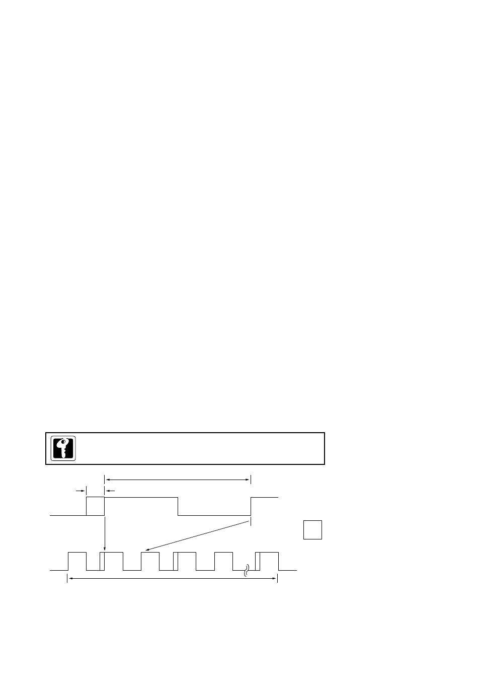
Figure 4-3-4 Pulse Added Type PWM Output
Chapter 4 Timer Functions
73
If bit 4 of port 1 is to be used as a
PWM output pin, set the P1DIR
and P1PLU registers.
PWM4 output is fixed at L with
X'FF' set at the lower 8
bits(TM40CL) of compare register.
Use of timer 4 at PWM mode
disables setting of X'FF' att
TM4OCL register.
,,
,
,,
,,
,,
,,
Added pulse
: Added pulse
Basic PWM components
Repeated 256 times
Tn=X'00'
Tn=X'01'
Tn=X'02'
Tn=X'03'
Tn=X'04'
Tn=X'FF'
,
Use a 16-bit access instruction to set the TM4OCH, TM4OCL
register.
16-bit Timer Operation (timer 4)