3 i/o port configuration and functions – Panasonic MN101C00 User Manual
Page 61
Chapter 3 Port Functions
47
I/O Port Configuration and Functions
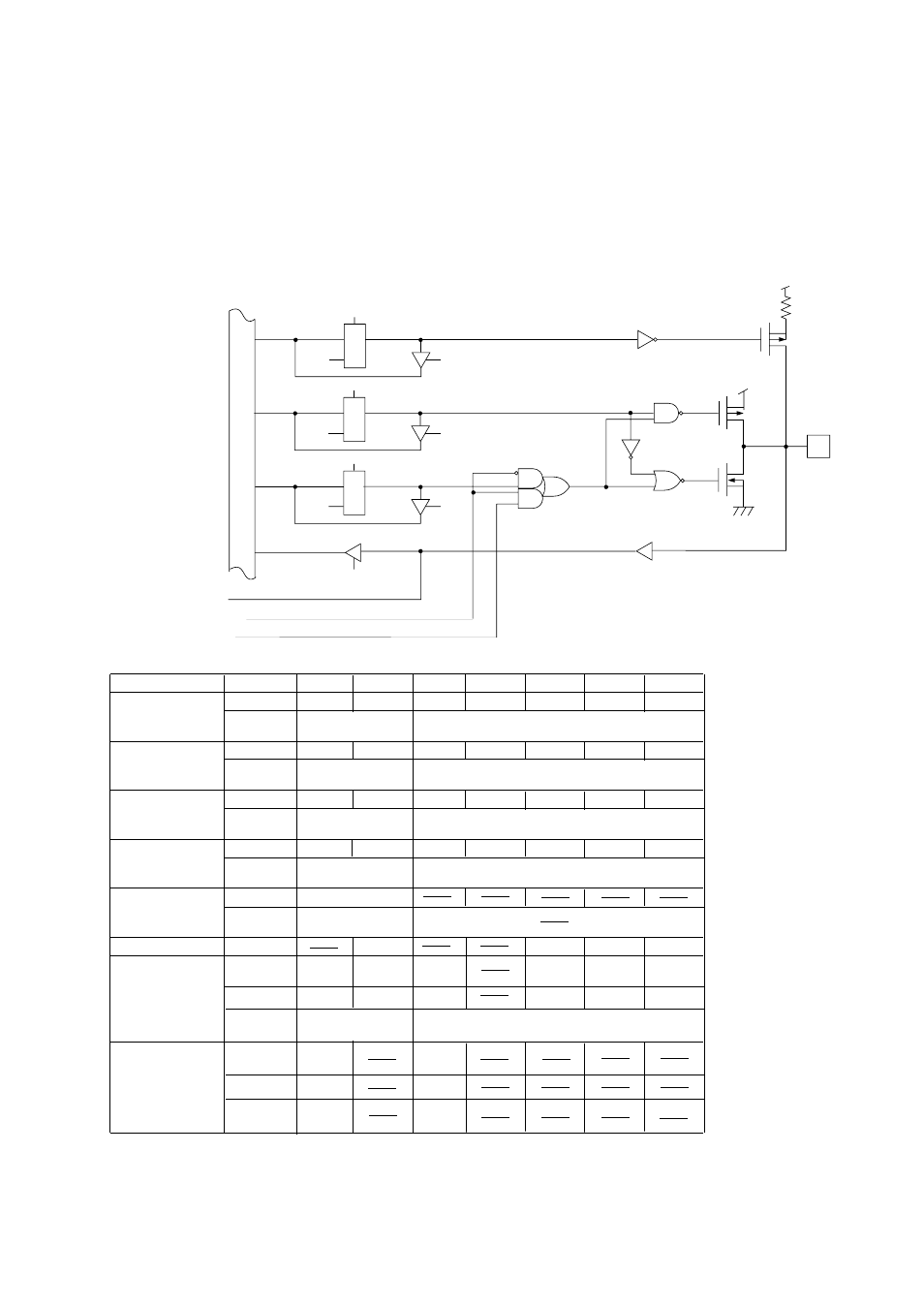
3-3 I/O Port Configuration and Functions
■
P00,P02,P10 to P14
R
D
L
Q
Reset
Write
Read
Read
R
D
L
Q
Reset
Write
Read
R
D
L
Q
Reset
Write
Read
Pull-up resistor control
I/O direction control
Port output data
Special function input data
Port input data
Data bus
Schmidt trigger input
Special function output control
Special function output data
SBO0(TXD)
P0PLU0
P00
P0PLU2
P02
P0PLU
(X'03F40')
P0DIR
(X'03F30')
P0OUT
(X'03F10')
P0IN
(X'03F20')
SC0MD3
(X'03F53')
SC0MD3
(X'03F53')
P0DIR0
P0DIR2
P0OUT0
P0OUT2
P0IN0
P0IN2
SC0SBOM
SBO0/TXD
SC0CMD
SC0CTR
(X'03F54')
SC0SBTM
SBT0
SC0SBOS
SC0SBTS
P1PLU0
P1PLU
(X'03F41')
P1DIR
(X'03F31')
P1OUT
(X'03F11')
P1IN
(X'03F21')
P1OMD
(X'03F39')
P1PLU1
P1PLU3
P1PLU4
P1DIR0
P1DIR1
P1DIR3
P1DIR4
P1OUT0
P1OUT1
P1OUT3
P1OUT4
P1IN0
P1IN1
P1IN3
P1IN4
RMOUT
TM3I
TM4I
P13TCO
P14TCO
P1PLU2
P1DIR2
P1OUT2
P1IN2
TM2I
P12TCO
P10
P11
P12
P13
P14
RMOEN
RMCTR
(X'3F89)
∗
Both The TM0RM flag of the RMCTR register and the P10TCO flag of the P10MD register
are used to switch between remote control output and timer output.
Pull-up
resistor
control
I/O
direction
control
Port
output
Port
input
Output
format
control
Special
function
output
control (1)
Control bit
Register
(address)
Control bit
Register
(address)
Control bit
Register
(address)
Control bit
Register
(address)
Control bit
Register
(address)
Control bit
Special
function
Special
function
Register
(address)
Special
function
output
control (2)
Control bit
Special function
Register
(address)
Special function input
SBT0
RMOUT
P10TCO
TM2O
TM3O
TM4O