5-2 operating conditions, Ta=–40, 85°c v – Panasonic MN101C00 User Manual
Page 28: 5v v, Osc1 is the cpu clock t, Xi is the cpu clock
Chapter 1 Overview
14
Electrical Characteristics
1-5-2 Operating Conditions
Ta=–40
to
+85°C V
DD
=2.0
to
5.5V V
SS
=0V
Note:
*1. Only for 48-QFH package
∗
2
t
c1
, t
c2
, t
c3
: OSC1 is the CPU clock
t
c4
: XI is the CPU clock
Parameter
Symbol
Conditions
Rating
Unit
MIN
TYP
MAX
Supply voltage
1
V
DD1
fosc
≤
20.0MHz
4.5
5.5
2
Supply voltage
V
DD2
fosc
≤
8.39MHz
2.7
5.5
V
3
during operation
V
DD3
fosc
≤
2.00MHz
2.0
5.5
4
V
DD4
*
1
fx = 32.768kHz
2.0
5.5
5
Voltage to maintain RAM data V
DD5
STOP mode
1.8
5.5
Operating speed
∗
2
6
tc1
V
DD
=4.5
to
5.5V
0.100
7
Instruction execution time
tc2
V
DD
=2.7
to
5.5V
0.238
µs
8
tc3
V
DD
=2.0
to
5.5V
1.00
9
tc4 *
1
V
DD
=2.0
to
5.5V
40
125
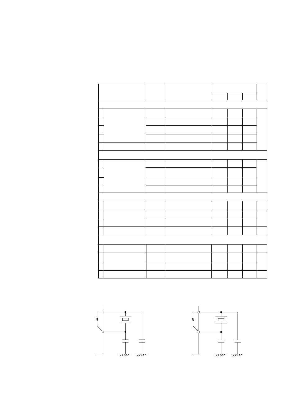
Crystal oscillator 1
Fig. 1-5-1
10 Crystal frequency
fxtal 1
V
DD
=4.5
to
5.5V
1.0
20.0
MHz
11
External capacitors
C
11
20
pF
12
C
12
20
13 Internal feedback resistor RF10
700
k
Ω
Crystal oscillator 2
Fig. 1-5-2*
1
14 Crystal frequency
fxtal 2
32.768
kHz
15
External capacitors
C
21
20
pF
16
C
22
20
17 Internal feedback resistor RF20
4.0
M
Ω
OSC1
700k
Ω
Typ
OSC2
MN101C
fxtal1
C12
C11
XI
4.0M
Ω
Typ
XO
MN101C
fxtal2
C22
C21
The instruction cycle is twice the clock cycle.
The feedback resistor is built-in.
Figure 1-5-1 Crystal Oscillator 1
The instruction cycle is four times the clock cycle.
The feedback resistor is built-in.
Figure 1-5-2 Crystal Oscillator 2
*1