Panasonic MN101C00 User Manual
Page 53
Chapter 3 Port Functions
39
Overview
■
Port 1 (P1)
5-bit CMOS tri-state I/O port.
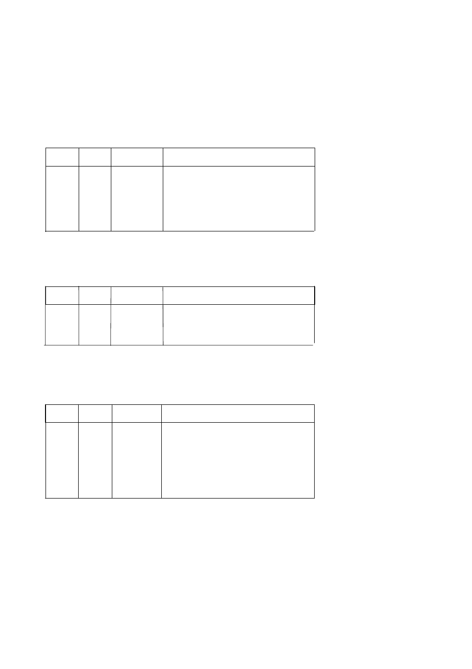
Table 3-1-3 Port 1 Functions
■
Port 2 (P2)
4-bit CMOS tri-state input port.
Table 3-1-4 Port 2 Functions
■
Port 6 (P6)
8-bit CMOS tri-state I/O port.
Table 3-1-5 Port 6 Functions
P10 to P14
I/O
RMOUT,
TM2IO to TM4IO
Each bit can be set individually as either an input or
output by the P1DIR register. A pull-up resistor for each
bit can be selected individually by the P1PLU register.
At reset, the input mode is selected and pull-up resistors
are disabled (high impedance output).
Pin Name
Type
Dual Function
Description
Pin Name
Type
Dual Function
Description
P20 to P23
Input
IRQ0,
IRQ1(SENS),
IRQ2 to 3
A pull-up resistor for each bit can be selected individually
by the P2PLU register. At reset, the input mode pull-up
resisters are disabled (high impedance output).
Only 48-QFH has P23.
Pin Name
Type
Dual Function
Description
Each bit can be set individually as either an input or
output by the P6DIR register. A pull-up resistor for each
bit can be selected individually by the P6PLU register. At
reset, the input mode pull-up resisters are disabled (high
impedance output).
P60 to P67 I/O