Panasonic MN101C00 User Manual
Page 23
Chapter 1 Overview
9
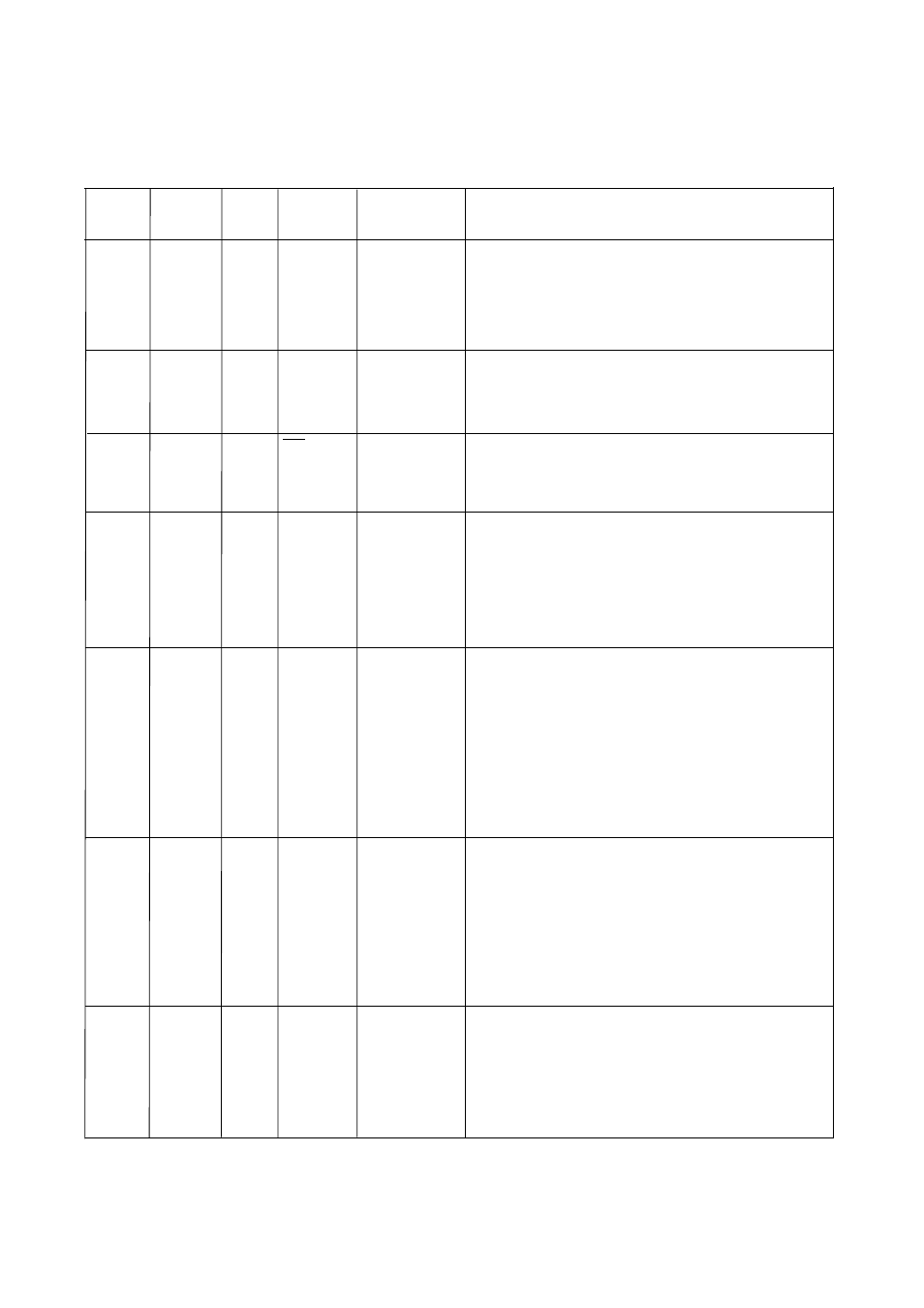
Table 1-3-1 Pin Function Summary (2/4)
41 to 42
P70 to P71 I/O
I/O port 7
2-bit CMOS tri-state I/O port.
Each individual bit can be switched to an input or output by the P7DIR
register. A pull-up or pull-down resistor for each bit can be selected
individually by the P7PLUD register.
However, pull-up and pull-down resistors cannot be mixed.
At reset, the input mode is selected and pull-up resistors are disabled (high
impedance output).
P70 and P71 pins do not exist for 42-SDIP package. P71 pin does not exist
for 44-QFP package, either.
1 to 4
P80 to P87 I/O
LED0 to 7
I/O port 8
45 to 48
8-bit CMOS tri-state I/O port.
Each individual bit can be switched to an input or output by the P8DIR
register. A pull-up resistor for each bit can be selected individually by
the P8PLU register. When configured as outputs, these pins can drive
LED segments, directly.
At reset, the input mode is selected and pull-up resistors for P80 to P87
are disabled (high impedance output).
Pins
33 to 40
P60 to P67
I/O
I/O port 6
8-bit CMOS tri-state I/O port.
Each bit can be set individually as either an input or output by the P6DIR
register. A pull-up resistor for each bit can be selected individually by the
P6PLU register. At reset, the input mode is selected and pull-up resistors
for P60 to P67 are disabled (high impedance output).
Pin No.
Name
Type
Dual Function
Function
Description
24 to 28
P10 to P14
I/O
RMOUT,
I/O port 1
TM2IO to
TM4IO
29 to 32
P20 to P23
Input
IRQ0,
Input port 2
IRQ1(SENS),
IRQ2 to 3
43
P27
Input
RST
Input port 2
5-bit CMOS tri-state I/O port.
Each bit can be set individually as either an input or output by
theP1DIR register. A pull-up resistor for each bit can be selected
individually by the P1PLU register. At reset, the input mode is
selected and pull-up resistors are disabled (high impedance output).
4-bit input port. A pull-up resistor for each bit can be selected
individually by the P2PLU register. At reset, the input mode is
selected and pull-up resistors are disabled (high impedance output).
P23 pin does not exist for 42-SDIP, 44-QFP packages.
Port P27 has an n-channel open-drain configuration. When "0" is
written and the reset is initiated by software, a low level will be
output.
8-bit input port.
A pull-up or pull-down resistor for each bit can be selected
individually by the PAPLUD register. However, pull-up and pull-
down resistors cannot be mixed.
At reset, the PA0 to PA7 input mode is selected and pull-up resistors
are disabled.
6 to 13
PA0 to PA7 Input
AN0 to AN7
Input port A