5-3 dc characteristics, Ta=–40 to +85°c v, 0 to 5.5v v – Panasonic MN101C00 User Manual
Page 31: The input pins are fixed at v, And the osc1 and xi pins are unconnected, The items i, And i, Are applicable only for 48-pin qfh package
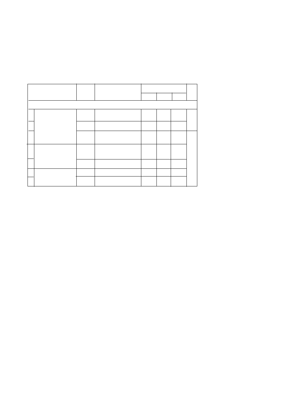
1-5-3 DC Characteristics
Ta=–40 to +85°C V
DD
=2.0 to 5.5V V
SS
=0V
Notes:
∗
1
Measured under conditions of Ta=25°C and no load.
The supply current during operation, I
DD1
(I
DD2
), is measured under the
following conditions: After all I/O pins are set to input mode and the oscillation
is set to
SS
, the input pins are
fixed at V
DD
, and a 20MHz (8.39MHz) square wave of amplitude V
DD
,V
SS
is input
to the OSC1 pin.
The supply current during operation, I
DD3
, is measured under the following
conditions: After all I/O pins are set to input mode and the oscillation is set to
SS
, the input pins are fixed at V
DD
,
and a 32.768kHz square wave of amplitude V
DD
,V
SS
is input to the XI pin.
The supply current during HALT mode, I
DD5
(I
DD6
), is measured under the
following conditions: After all I/O pins are set to input mode and the oscillation
is set to
SS
, the input pins are fixed
at V
DD
, and an 32.768kHz square wave of amplitude V
DD
,V
SS
is input to the XI
pin.
The supply current during STOP mode I
DD7
(I
DD8
) is measured under the following
conditions: After the oscillation mode is set to
fixed at V
SS
, the input pins are fixed at V
DD
, and the OSC1 and XI pins are
unconnected.
*2
The items I
DD5
(I
DD6
) and I
DD7
(I
DD8
) are applicable only for 48-pin QFH package.
Parameter
Symbol
Conditions
Rating
Unit
MIN
TYP
MAX
Supply current (no load at output)
∗
1
1 Supply current
I
DD1
fosc=20.0MHz,V
DD
=5V
25
60
mA
2 during operation
I
DD2
fosc=8.39MHz,V
DD
=5V
10
25
3
I
DD3
*2
fx =32.768kHz,V
DD
=3V
100
4
Supply current during HALT mode
I
DD5
*2
fx =32.768kHz,V
DD
=3V
8
Ta=25
?W2@6X
?7
?@e?@f?O2@@6T2@?f
?3=?C5e?W2(M??I4@@Lf
?V4@0YeW&(Yf?I'1f
7@H?gV'f
?J@5hg
?7@Hhg
?@@?hg
?@@?hg
?@@?hg
?@@?hg
?@@?hg
?@@?hg
?3@Lhg
?N@1h?@f
3@L?gJ5f
V')Xf?W.Yf
?V4)K?eO.Y?f
?I4@@@0Yg
5
I
DD6
*2
Ta=-40
to
85˚C
µA
6
Supply current during STOP mode
I
DD7
V
DD
=5V, Ta=25˚C
0
2
7
I
DD8
V
DD
=5V, Ta=-40
to
85˚C
0
20
Chapter 1 Overview
17
Electrical Characteristics
18