Panasonic MN101C00 User Manual
Page 85
Chapter 4 Timer Functions
71
16-bit Timer Operation (timer 4)
If TM4IO input is selected as the
clock source and the value of
binary counter 4 is to be read
during operation, select
synchronized TM4IO input to avoid
reading data that may be
incomplete during count-up
transitions. However, with
synchronized TM4IO input, it is not
possible to return from
STOP/HALT modes.
■ Event Count Function
Settings for the event count function are listed below.
(1)
Set the TM4EN flag of the timer 4 mode register (TM4MD) to "0" to stop the count
operation of timer 4.
(2)
Use the TM4CK2 to 0 flags of the TM4MD register to select TM4IO input or
synchronized TM4IO input as the clock source.
(3)
Set the TM4PWM flag of the TM4MD register to "0" so that 16-bit timer operation
is selected.
(4)
Set a value in compare register 4 (TM4OCH, TM4OCL).
(5)
Set the TM4EN flag of the TM4MD register to "1" to start the timer.
(6)
When timer 4 begins operation, binary counter 4 will count upward from X'0000'.
(7)
When the value of binary counter 4 matches that of the TM4OCH and TM4OCL
registers, the timer 4 interrupt request flag is set, and the binary counter 4 is reset to
X'0000' and begins to count upward again.
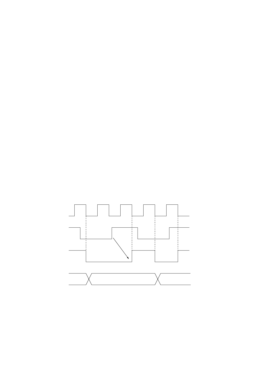
When synchronized TM4IO is selected, the timer 4 clock source is synchronized with the system
clock after a transition of the TM4IO input signal. Timer 4 counts upward based on a signal
synchronized to the system clock. Therefore, correct values can be read from binary counter 4.
Figure 4-3-2 Timer 4 Event Counter Timing (when synchronous TM4IO
input is selected)
CPU system clock
(fs)
TM4IO input
Synchronous
circuit output
Binary counter
n
n+1