Powerware 9315 User Manual
Page 49
A---5
Powerware 9315 Parallel Redundant System I & O
164202013 Rev. D 041599
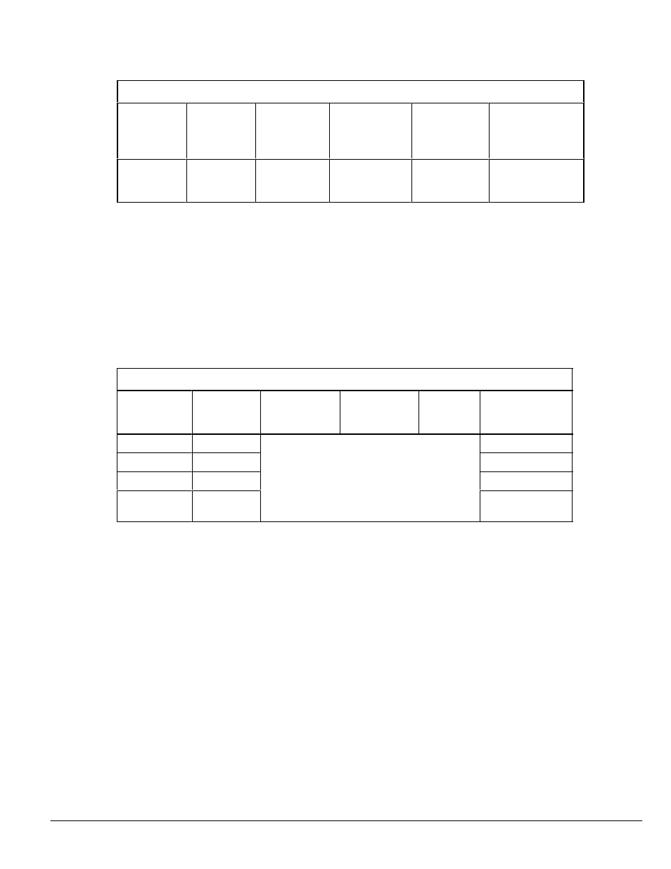
Table A--1. Control Wiring Requirements and Termination Requirements
Connection
Points in Tie
Cabinet
Size of
Pressure
Termination
(lb-in)
Maximum
Voltage and
Current
Connection
Points in UPS
Size of
Pressure
Termination
(lb-in)
Recommended
Wiring Size
TB1--1
through
TB1--7
#18--#8,
(55)
24V, 0.25A
TB3--1 through
TB3--7
#22--#12,
(5--7)
#18--#12
Notes for Table A---1:
1.
Install the control wiring in separate conduit from the power wiring. Only copper
wire or tinned copper wire should be used.
2.
Control wiring is NEC class 2 (IEC 950 SELV).
3.
Class 1 methods are recommended for control wiring.
4.
Control wiring should be twisted pairs and twisted triple as shown in Figure 9.
Table A--2. UPS Power Cable Terminations and Connection Points
Connection
Point in UPS
Function
Size of
Pressure
Termination
Tightening
Torque
N--M (lb--in)
Int Hex
Size (In.)
Connection Point
in Tie Cabinet
E9
Phase A
E9
E10
Phase B
Refer to the applicable Powerware 9315
E10
E11
Phase C
Refer to the applicable Powerware 9315
UPS installation manual for this information
E11
E12
Neutral/
Gnd
UPS installation manual for this information
E12