Chapter 2 installing the parallel redundant system, Installing the parallel redundant system – Powerware 9315 User Manual
Page 21
15
Powerware 9315 Parallel Redundant System I & O
164202013 Rev. D 041599
Installing the Parallel
Redundant System
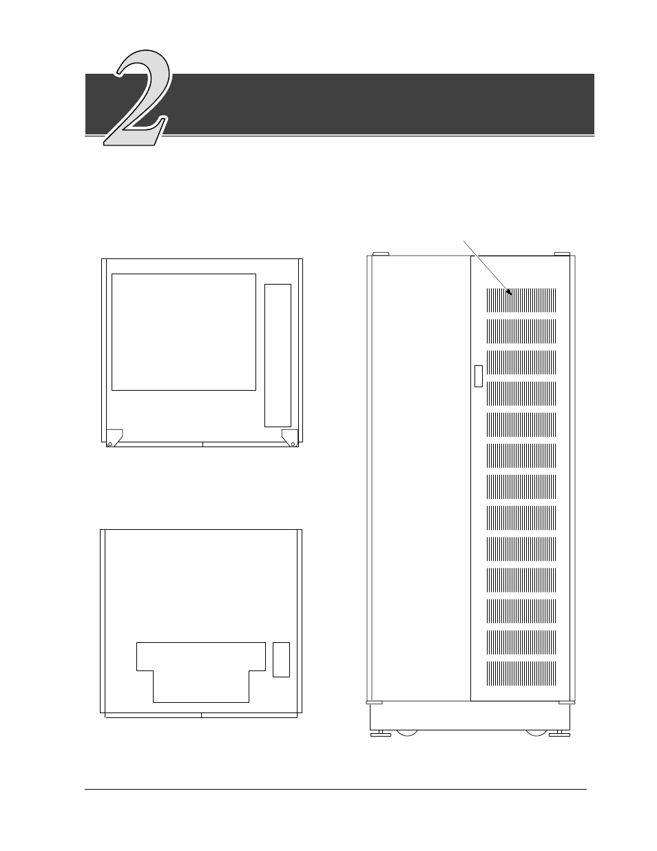
Once the parallel cabinet has been moved to its installed location, unpacked, and
inspected, it is ready for installation. This manual discusses the typical
configuration of installing the parallel cabinet in a remote location. The parallel
cabinet arrives as shown in Figure 5.
Cable Entry, Top View
Cable Entry, Floor Plan View
Bottom Wire Entry
Cooling Grate
Top
Wire
Entry
Cooling Air Inlets
(Cooling Air Outlets)
Figure 5. Top, Bottom, and Front View of Parallel Cabinet