Do not tilt the cabinet more than, 10˚ during installation – Powerware 9315 User Manual
Page 22
16
Powerware 9315 Parallel Redundant System I & O
164202013, Rev. D 041599
Refer to the following while installing the parallel cabinet:
·
Dimensions in this manual are in millimeters and inches.
·
Do not tilt the cabinet more than
10˚ during installation.
·
The conduit landing plates are to be removed to add conduit landing holes as
required. Plate material is 16 gauge steel (0.06 in. thick).
·
Terminals E9–E12 and E16---E18 are UL and CSA rated at 90˚C. A hex key tool
is required to attach wires to the terminals.
·
Details about control wiring are provided in Table A---1 of Appendix A and the
Control Wiring Interconnect Details in Chapter 3 of this manual.
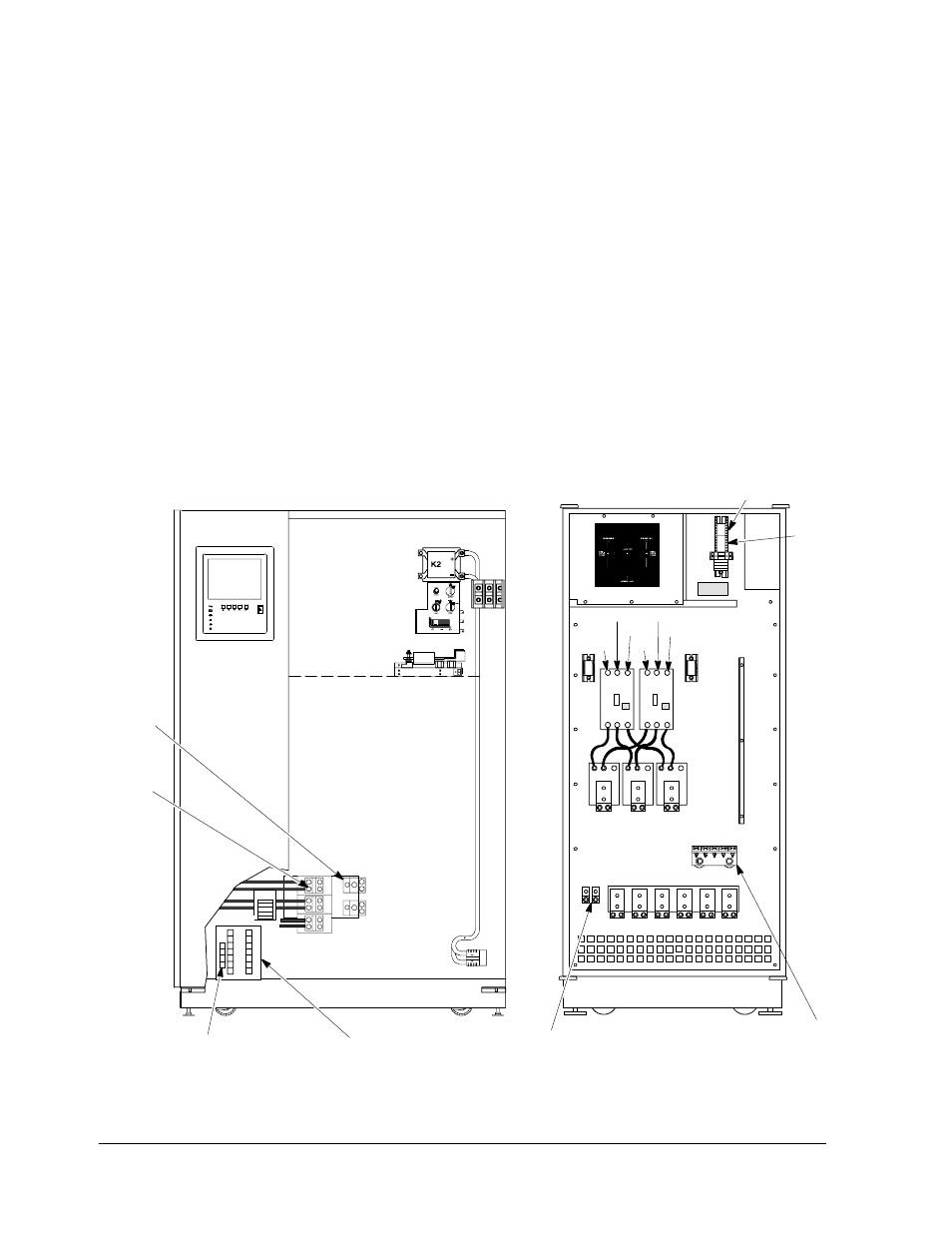
Figure 6 shows typical control wiring and power wiring terminations of the UPS
module and parallel cabinet. Refer to the Powerware 9315 Installation manual
provided with the UPS system for location of UPS module cabinet wiring
terminations.
NOTE: Material and labor for external wiring are to be provided by designated
personnel.
LEFT DOOR
Output
Neutral
Connection
(E12)
TB1
TB2
MOB#2
TB1
Ground
MOB1
E10
E9
MOB#1 TB1
E11
E9
MOB2
E16 E17 E18
E12
E10
E11
ÆA ÆC
ÆB
ÆA ÆC
ÆB
A/C Output
E9, E10,
E11
UPS MODULE
PARALLEL CABINET
Communication Panel
Terminal Strip
TB3
(100--160kVA UPS Shown)
Isolated
Ground
(Optional)
Figure 6. Typical Control and Power Wiring Terminations of UPS Module
and Parallel Cabinet