Location of tb3 in ups modules – Powerware 9315 User Manual
Page 48
A---4
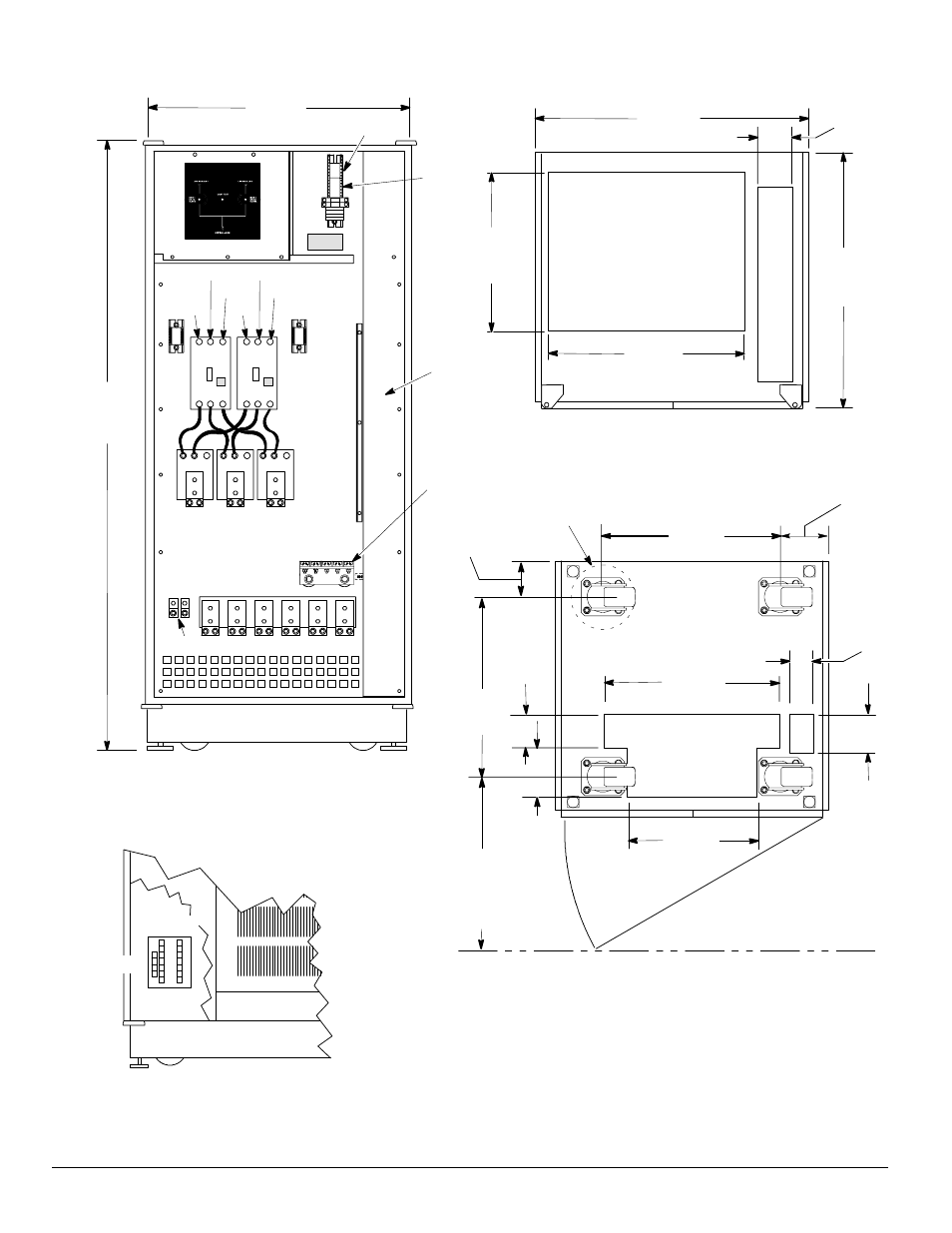
Powerware 9315 Parallel Redundant System I & O
164202013, Rev. D 041599
TB3
Parallel Cabinet
Terminal Locations
Parallel Cabinet Cable Entry,
Top View
Parallel Cabinet Cable
Entry, Floor Plan View
Cooling Grate
Top
Wire
Entry
TB1 TB2
Location of TB3
in UPS Modules
MOB#2
TB1
Ground
MOB1
E10
E9
MOB#1
TB1
E11
E9
MOB2
E16
E17
E18
E12
E10
E11
ÆA ÆC
ÆB
ÆA ÆC
ÆB
853.8
(33.6)
1870.0
(73.6)
853.8
(33.6)
800.0
(31.5)
606.30
(23.88)
115.32
(4.54)
339.85
(13.38)
Bottom Wire Entry
518.92
(20.43)
369.82
(14.56)
111.76
(4.40)
50.04
(1.97)
130.05
(5.12)
100.08
(3.94)
545.42
(21.5)
142.40
(5.61)
88.90 (3.50)
Swivel Radius
560.63
(22.07)
122.70
(4.83)
914.40 (36.00)
Minimum Clearance
For Subassembly
Removal
Wire Way
Dimensions are in millimeters (inches)
Overall width dimensions include side panels.
Subtract 25 mm (1 in) for each side panel for
line up and match.
Isolated
Ground
(Optional)
Figure 13. Electrical Access Details