Master modules, M1, m2 – Peavey V12 User Manual
Page 40
p. 40
master modules
—M1, M2
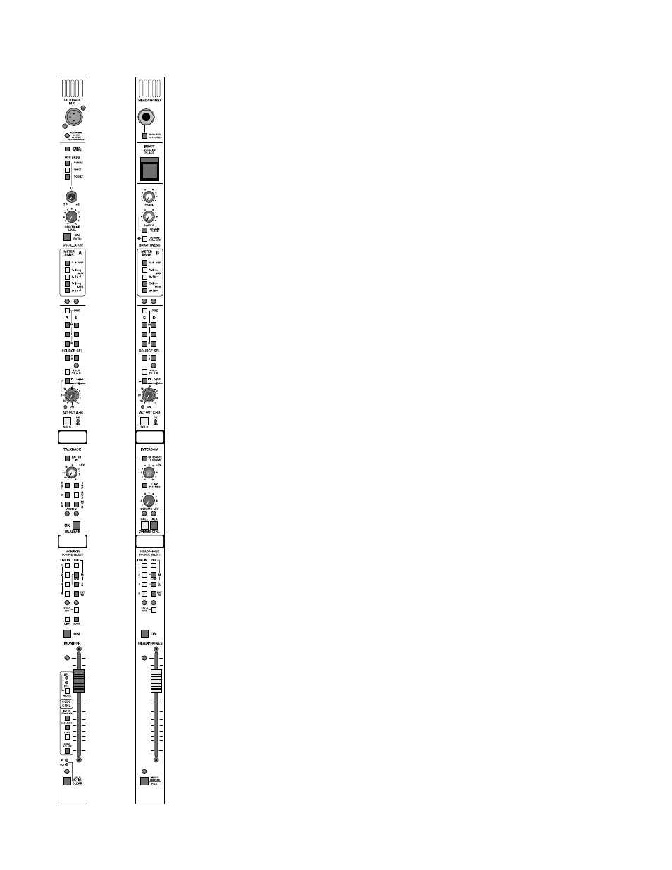
alternate output features
Alternate output A-B are located on the left master module and Alternate
output C-D are located on the right master module. Controls provided
on the left and right module alternate outputs are identical. This section is
intended for miscellaneous signal outputs including dressing room feeds,
broadcast production monitor feeds, sub output feeds, delay speaker
stacks, back of stage feeds, etc. Each module contains the following con-
trols:
source-pre
Selects between the default post fader signal level and a pre fader level.
This switch will affect both the odd and even signal sources.
left-select switch
Selects the Left main signal. Separate switches to A (C) and B (D) outputs.
This allows for generation of summed and reversed signal outputs.
right-select switch
Selects the Right main signal. Separate switches to A (C) and B (D) out-
puts. This allows for generation of summed and reversed signal outputs.
mono-select switch
Selects the Mono main signal. Separate switches to A (C) and B (D) out-
puts. This allows for generation of summed LCR and reversed image sig-
nal outputs.
solo to A-B (C-D)
Puts the contents of the Solo bus on outputs A-B and/or C-D.
stereo switch
Reconfigures the dual concentric level control fro dual mono function to
Stereo level and Balance control.
peak and signal-present indicator
Monitors signal levels of the pair of outputs. Green signal present LED
indicator is dynamic and varies in intensity. Should any signal level approach
3dB of clipping, the red Peak LED indicator will illuminate.