Troubleshooting – Lochinvar Power-fin 1701 User Manual
Page 40
3
Troubleshooting
40
Service Manual
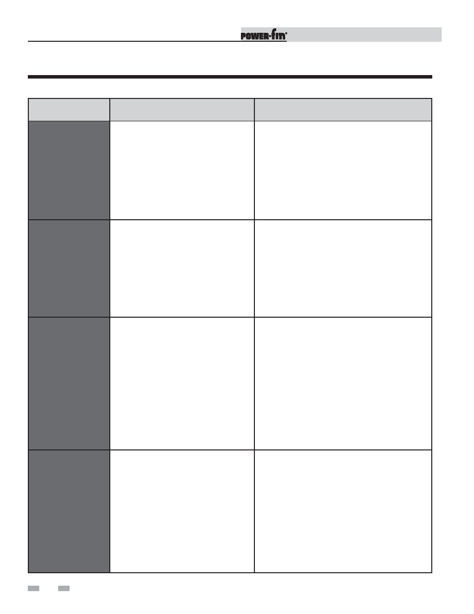
FAULT
DESCRIPTION
CORRECTIVE ACTION
APS Open
(Lockout will reset
automatically after 5
minutes or may be reset
immediately once
condition has been
corrected. Press the
RESET button on the
SMART SYSTEM display
to reset.)
The air pressure switch did not make within
1 minute after the combustion air blower has
been energized.
• Check air filter. Clean or replace as necessary.
• Vent/air intake lengths exceed the maximum allowed
lengths.
• Check for blockage or obstruction in vent/air inlet pipe
or at terminations.
• Verify combustion air blower is operating. Replace if
necessary.
APS Closed
(Lockout will reset
automatically after 5
minutes or may be reset
immediately once
condition has been
corrected. Press the
RESET button on the
SMART SYSTEM display
to reset.)
The SMART SYSTEM control sensed that
the air pressure switch was closed before the
combustion air blower was energized.
• Check for jumper on air pressure switch.
• Check for an unusually high negative draft in the vent
stack.
Wrong ID Plug
Control module ID plug does not match
parameter L5.
• Verify that ID plug is connected properly to connector
X5 on the control module.
• Verify that the wiring in the ID plug is not cut or
damaged and that the wiring connectors are seated
properly in the plug.
• Verify that the number on the ID plug matches the
number in parameter L5. If not, replace the control
module.
• When replacing control modules, verify that the
number in parameter L5 matches the number on the
ID plug. If so, press the ENTER button on the SMART
SYSTEM display. If not, replace the control module.
Temp O/Shoot
(Lockout will reset
automatically after 5
minutes or may be reset
immediately once
condition has been
corrected. Press the
RESET button on the
SMART SYSTEM display
to reset.)
The stack temperature has exceeded the set
parameters for the boiler/water heater.
• Inspect the heat exchanger. Reference page 30 of
this manual for the procedure on how to clean the flue
side of the heat exchanger.
• Inspect the flue sensor and associated wiring.
Measure the resistance of the flue sensor and
compare to Table 3C on page 33 of this manual.
Replace the sensor if necessary.
• Verify that the vent/air intake pipes are properly
installed and that there are no obstructions.
• Replace the main control board.
Table 3F (continued from previous page) Troubleshooting Chart - Fault Messages Displayed on Operator Interface