Maintenance, Gas valve adjustment procedure – Lochinvar Power-fin 1701 User Manual
Page 29
2
Maintenance
Service Manual
29
2
Maintenance
(continued)
Gas valve adjustment procedure
1.
Turn the appliance power switch to the “OFF” position.
2.
Loosen the thumbscrew on the upper left access panel.
Remove the upper left access panel.
3.
Remove the screws along the front and rear edge of the
top outer jacket panel. Disconnect the 2-pin connector
hanging from the top panel cover inside the unit.
Remove the top outer jacket panel.
4.
Follow the Combustion Analysis Procedure on page 28
of this manual to measure combustion.
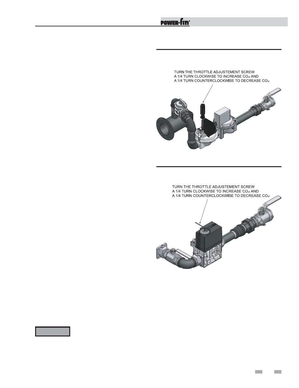
5.
With the appliance operating in the Service Mode,
locate the throttle adjustment screw on the gas valve.
See FIG. 2-5 for F9 models and FIG. 2-6 for B9/M9
models. Using a screwdriver (F9) or Allen wrench
(B9/M9) turn the throttle adjustment screw a 1/4 turn
clockwise to increase CO
2
levels and a 1/4 turn
counterclockwise to decrease CO
2
levels.
6.
After one adjustment of the valve, measure the
combustion.
7.
If the combustion is still not within the specified range,
repeat the procedure. This procedure SHOULD NOT
be performed more than four (4) times. If after four
(4) adjustments the combustion is still not within the
specified range, revisit the possible causes in Table 2D
on page 28 of this manual.
8.
Once the combustion analysis is complete, press the
ENTER/RESET button on the display board to take the
appliance out of Service Mode. The appliance will go
to shutdown and the display will show HTR:OFF.
9.
Turn the appliance power switch to the “OFF” position.
10. Replace the flue temperature sensor into the flue pipe.
11. Replace the top jacket panel and reconnect the 2-pin
connector hanging from the top panel cover.
12. Replace the upper left access panel.
13. Turn the appliance power switch to the “ON” position.
14. Press the ENTER/RESET button on the display board
until HTR:Standby appears in the display window.
Figure 2-5_Throttle Adjustment Screw - F9 Model
Figure 2-6_Throttle Adjustment Screw - B9/M9 Models
ƽ WARNING
Overfire and underfire hazards! Possible
fire, explosion, overheating, and
component failure. Do not attempt to
adjust firing rate of the boiler or water
heater. The firing rate must be adjusted
only by factory trained personnel.