Service – Lochinvar Power-fin 1701 User Manual
Page 19
Service Manual
19
H: Control modes
SH controlling sensor (boiler only)
The SH controlling sensor parameter selects the sensor the
control will use to regulate the boiler firing rate. This parameter
is adjustable by the installer by accessing parameter H1. The
sensor selections are as follows: The outlet sensor regulates the
firing rate based on the outlet water temperature of the unit and
the inlet sensor regulates the firing rate based on the inlet water
temperature of the unit. If the outlet sensor is selected, and the
optional system supply sensor is connected, the control will
regulate the firing rate based on the system sensor temperature.
If the inlet sensor is selected, and the optional system return
sensor is connected, the control will regulate the firing rate
based on the system return sensor. The default sensor is the
Outlet Sensor.
Enable input
The boiler or water heater can receive a call for heat in two
different ways. First, an external contact (like a tank thermostat)
or sensor (like a tank sensor) can generate a call for heat.
Second, the 0-10Vdc voltage from a BMS can be used to
generate the call for heat, as well as provide the set point or
modulation level. On boilers, the external contact is connected
to the Enable input on the low voltage connection board. On
water heaters, the external contact is connected to the Tank
Thermostat input on the low voltage connection board. When
a tank sensor is connected, the Tank Thermostat input is not
used. When the call for heat comes from an external contact or
tank sensor, the enable input must be set to active. When the
call for heat comes from the 0-10Vdc input, the enable input
must be set to inactive. This setting is adjustable by the installer
by accessing parameter H2. The default setting is active.
0-10V building management input (BMS)
When the building management input is enabled, the control
modulates the unit (B9 or M9 only) or the cascade based on the
voltage on the 0-10V input on the connection board. The 0-
10V input may control either the modulation of the unit(s), or
the set point. This setting is adjustable by the installer by
accessing parameter H3. The default value is Inactive. See
menu Section J to adjust the parameters that control the BMS
operation.
Cascade
The boiler or water heater is part of a group of units sequenced
together. The designated Leader unit determines the total
output needed from the group based on the set point and
controlling sensor reading. It assigns portions of the output to
itself (Leader) and the Member units. When Cascade is active,
each boiler in the group requires a unique address (see menu
Section I below). This setting is adjustable by the installer by
accessing parameter H4. The default value is Inactive.
I: Cascade
Boiler cascade address
The boiler designated as the Leader needs to be programmed
with address 0. All the Member boilers require addresses from
1 to 7, and the addresses must be different for each Member.
The addresses can be in any order, regardless of the order in
which the units are wired together. This parameter is adjustable
by the installer by accessing parameter I1. The outdoor air (if
used) and system supply sensor must be connected to the Leader
boiler. The default address is 1.
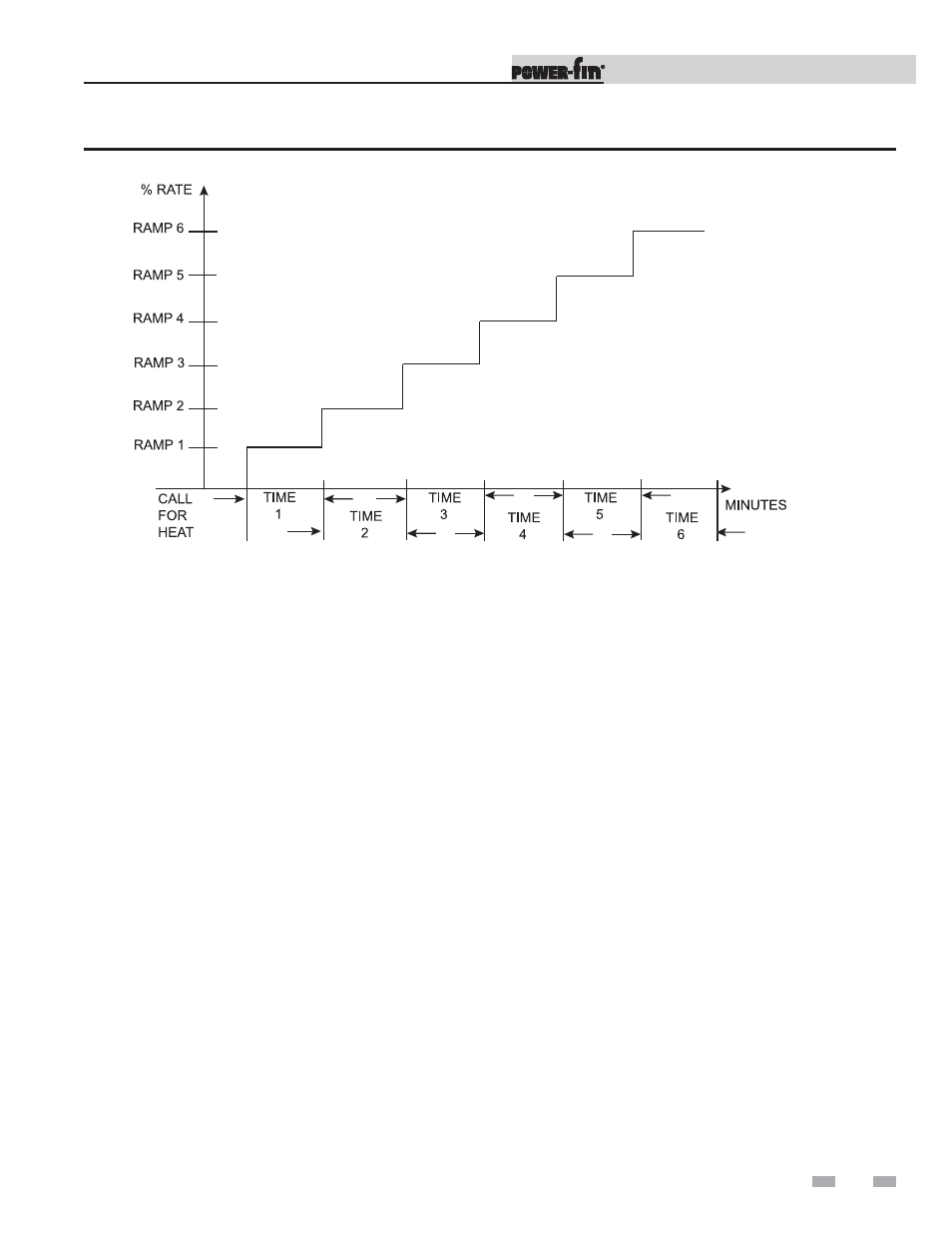
Figure 1-2_Ramp Delay Interval
1
Service
(continued)