Troubleshooting – Lochinvar Power-fin 1701 User Manual
Page 38
38
Service Manual
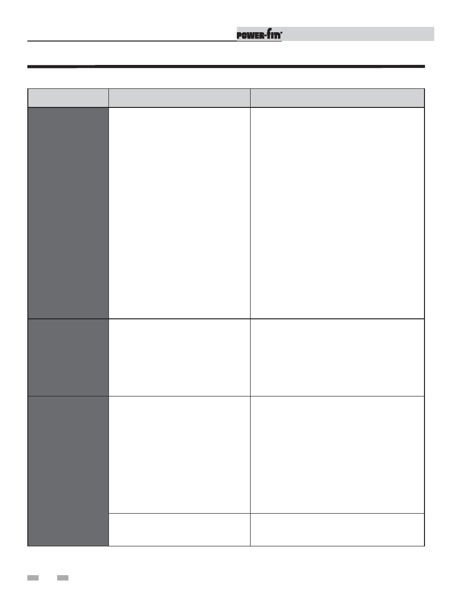
FAULT
DESCRIPTION
CORRECTIVE ACTION
Manual Reset
High Limit
(Will require a manual
reset once condition has
been corrected. Press
the RESET button on
the SMART SYSTEM
display to reset.)
The outlet water temperature has exceeded
the setting of the adjustable high limit.
• Verify setting of adjustable high limit.
• Verify that the system is full of water and that all air
has been properly purged from the system.
• Verify that the appliance is piped properly into the
system. Refer to Section 4 - Water Connections of
the Power-fin Installation and Operation Manual for
proper piping methods for the Power-fin.
• Check 120 VAC to the pump motor on a call for heat.
If voltage is not present, check wiring leading to the
main control board. Replace the main control board if
necessary.
• If 120 VAC is present on a call for heat and the pump
is not operating, replace the pump.
• If the system pump is a variable speed pump, ensure
the system flow is not less than the boiler flow.
• Check temperature setting of the main control board.
• Check resistance of water sensors and compare to
the tables on page 33 of this manual. Replace the
sensor if necessary.
• Replace high limit.
Inlet Low
The inlet water temperature did not exceed
130° within 15 minutes of ignition.
• Raise temperature set point above 130°.
• Install a 3-way valve per the piping diagram in
Section 4 - Water Connections of the Power-fin
Installation and Operation Manual.
• Replace the main control board.
Fan Low
OR
Fan Speed Low
(Will require a manual
reset once condition has
been corrected. Press
the RESET button on
the SMART SYSTEM
display to reset.)
The actual fan RPM is 30% lower than what
is being called for.
• Vent/air intake lengths exceed the maximum allowed
lengths. Refer to Section 2 - Venting of the
Power-fin Installation and Operation Manual for
proper lengths.
• Check for obstruction or blockage in the vent/air
intake pipes or at terminations.
• Check wiring connections at the fan and at the
main control board.
• Replace the fan.
• Replace the main control board.
Blown fuse.
• Replace fuse F3 on the main control board, see
page 31 of this manual.
Table 3F (continued from previous page) Troubleshooting Chart - Fault Messages Displayed on Operator Interface
3
Troubleshooting