Maintenance, Combustion analysis procedure – Lochinvar Power-fin 1701 User Manual
Page 28
2
Maintenance
28
Service Manual
10. Once the gas manifold pressure has been checked, press the
ENTER/RESET button on the display board to take the
appliance out of Service Mode. The appliance will go to
shutdown and the display will show HTR:OFF.
11. Turn the appliance power switch to the “OFF” position.
12. Remove the manometer and related fitting(s) from the
connection tap and replace the 1/8" hex plug (on F9 models
only).
13. Replace the top jacket panel and reconnect the 2-pin
connector hanging from the top panel cover.
14. Replace the upper left access panel.
15. Turn the appliance power switch to the “ON” position.
16. Press the ENTER/RESET button on the display board until
HTR:Standby appears in the display window.
Combustion analysis procedure
1.
Turn the appliance power switch to the “OFF” position.
2.
Remove the flue temperature sensor from the flue pipe.
Note:
Combustion measurements will be made at this
point.
3.
Turn the appliance power switch to the “ON” position.
4.
Place the appliance into the active position by pressing the
ENTER/RESET button on the display board (see page 5)
until HTR:Standby appears in the display window.
5.
Locate the pinhole button below the ENTER/RESET
button. Press the button once and hold for 5 seconds to
place the appliance into Service Mode. In Service Mode the
appliance will fire and operate at 100% of rate.
6.
Insert the probe from a combustion analyzer into the hole
left by the removal of the flue temperature sensor.
7.
Compare the combustion measurement to the values listed
in Table 2C.
Firing Control /
Model No.
Natural Gas
CO
2
(%)
LP Gas
CO
2
(%)
F9: 502 - 1302
7.9 to 8.4
9.0 to 9.5
B9: 1501 - 2001
8.0 to 8.5
9.0 to 9.5
M9: 502 - 1302
8.2 to 8.7
9.0 to 9.5
M9: 1501 - 1701
8.6 to 9.1
9.6 to 10.1
M9: 2001
7.6 to 8.2
8.6 to 9.2
Table 2C_Combustion Measurements
8.
If the combustion is not within the specified range,
reference the Troubleshooting Chart below for possible
causes and corrective actions.
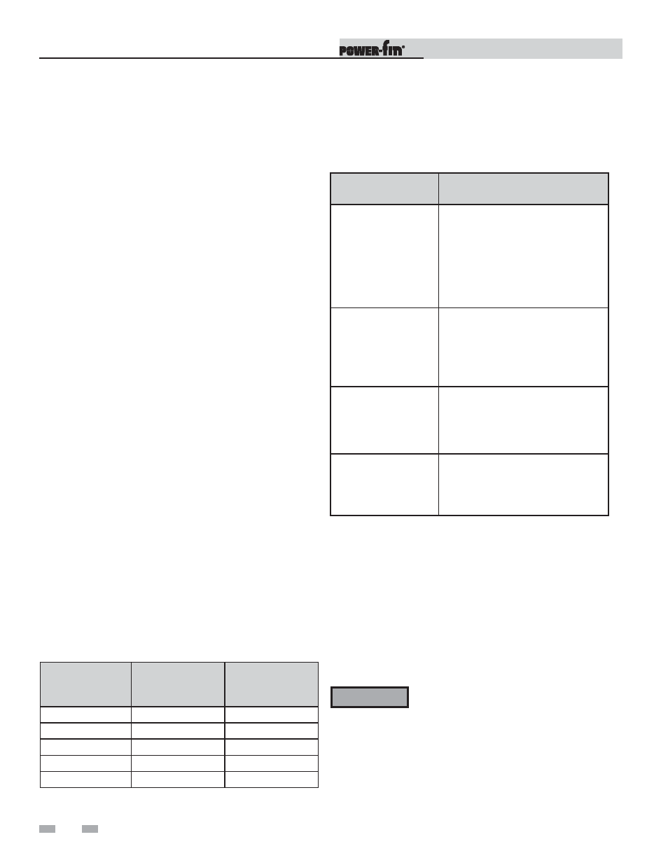
Possible Cause
Corrective Action
Vent / Air Intake
Length or Obstruction
-
Refer to Section 2 - Venting in the
Power-fin Installation and
Operation Manual for the proper
venting and air intake methods.
-
Check for obstructions in the
vent / air intake terminals.
Gas Supply Pressure
-
Refer to Section 3 - Gas
Connections in the Power-fin
Installation and Operation
Manual for the proper gas supply
for the Power-fin.
Dirty / Damaged
Burner
-
Refer to page 26 of this manual
for burner removal and cleaning
procedures.
-
Replace burner if necessary.
Gas Valve Adjustment
-
Refer to page 29 of this manual
for the gas valve adjustment
procedure.
Table 2D_Combustion Troubleshooting Chart
9.
Once the combustion analysis is complete, press the
ENTER/RESET button on the display board to take the
appliance out of Service Mode. The appliance will go to
shutdown and the display will show HTR:OFF.
10. Turn the appliance power switch to the “OFF” position.
11. Replace the flue temperature sensor into the flue pipe.
12. Turn the appliance power switch to the “ON” position.
13. Press the ENTER/RESET button on the display board until
HTR:Standby appears in the display window.
ƽ WARNING
You must replace the flue temperature sensor
to prevent flue gas spillage into the room.
Failure to comply could result in severe
personal injury, death, or substantial
property damage.