Sidewall direct venting, Vent/air termination – sidewall, Model kit number vent size – Lochinvar KBII-I-O REV C 81 - 286 User Manual
Page 21
21
Installation & Operation Manual
4
Sidewall direct venting
Vent/air termination – sidewall
Follow instructions below when
determining vent location to avoid
possibility of severe personal injury, death,
or substantial property damage.
A gas vent extending through an exterior
wall shall not terminate adjacent to a wall or
below building extensions such as eaves,
parapets, balconies, or decks. Failure to
comply could result in severe personal
injury, death, or substantial property
damage.
Installation must comply with local
requirements and with the National Fuel
Gas Code, ANSI Z223.1 for U.S.
installations or CSA B149.1 for Canadian
installations.
Determine location
Locate the vent/air terminations using the following
guidelines:
1. The total length of piping for vent or air must not exceed
the limits given in the General Venting Section on page 19
of this manual.
2.
You must consider the surroundings when terminating the
vent and air:
a.
Position the vent termination where vapors will
not damage nearby shrubs, plants or air
conditioning equipment or be objectionable.
b.
The flue products will form a noticeable plume as
they condense in cold air. Avoid areas where the
plume could obstruct window views.
c.
Prevailing winds could cause freezing of
condensate and water/ice buildup where flue
products impinge on building surfaces or plants.
d.
Avoid possibility of accidental contact of flue
products with people or pets.
e.
Do not locate the terminations where wind eddies
could affect performance or cause recirculation,
such as inside building corners, near adjacent
buildings or surfaces, window wells, stairwells,
alcoves, courtyards, or other recessed areas.
Do not exceed the maximum lengths of the
outside vent piping shown in FIG. 4-1B.
Excessive length exposed to the outside
could cause freezing of condensate in the
vent pipe, resulting in potential boiler
shutdown.
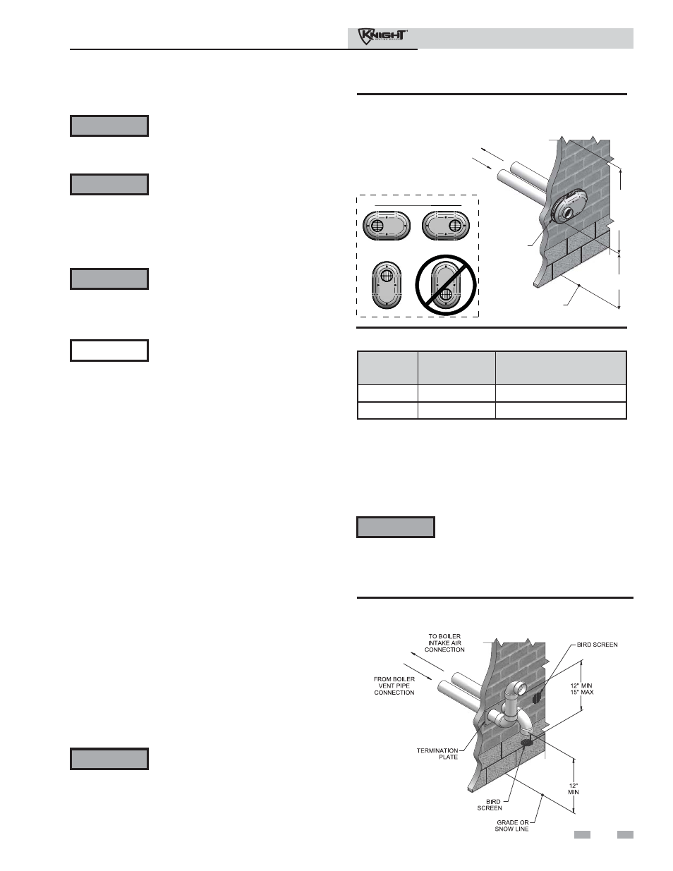
Figure 4-1B Alternate PVC/CPVC Sidewall Termination
of Air and Vent w/Field Supplied Fittings
ƽ WARNING
ƽ WARNING
NOTICE
ƽ WARNING
ƽ WARNING Do not connect any other appliance to the
vent pipe or multiple boilers to a common
vent pipe. Failure to comply could result in
severe personal injury, death, or substantial
property damage.
ƽ WARNING Sidewall vent and air inlet terminations
must terminate in the same pressure zone.
If using the alternate sidewall termination:
3. The air piping must terminate in a down-turned elbow as
shown in FIG. 4-1B. This arrangement avoids recirculation
of flue products into the combustion air stream.
4. The vent piping must terminate in an elbow pointed
outward or away from the air inlet, as shown in FIG. 4-1B.
f.
Do not terminate above any door or window.
Condensate can freeze, causing ice formations.
g.
Locate or guard vent to prevent condensate damage
to exterior finishes.
TO BOILER
INTAKE AIR
CONNECTION
FROM BOILER
VENT PIPE
CONNECTION
VENT / AIR
TERMINATION
GRADE OR
SNOW LINE
12"
MIN
12"
MIN
TO
OVER-
HANG
POSSIBLE ORIENTATIONS
Figure 4-1A PVC/CPVC Sidewall Termination of Air
and Vent
Model
Kit Number
Vent Size
81 - 211
KIT30045
3 inch vent
286
KIT30046
4 inch vent
Table 4A Sidewall Vent Kits