Laser drive control circuit – Lexmark 5021-0XX User Manual
Page 76
1-50
Service Manual
5021-0XX
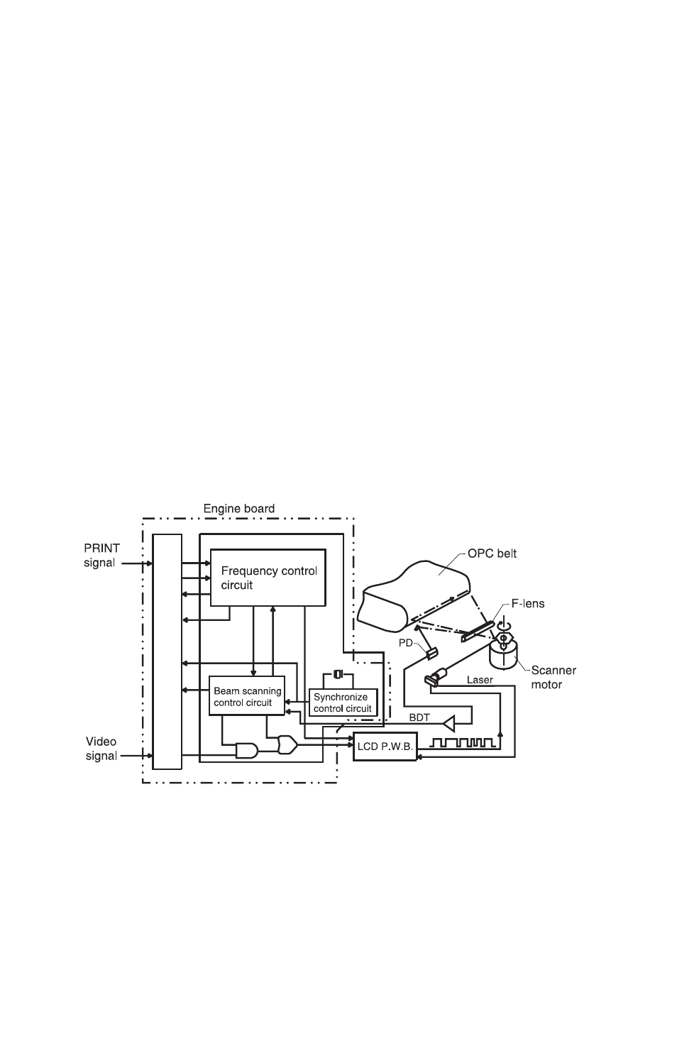
Laser drive control circuit
The laser drive control circuit (LDC) consists of a video signal input
circuit, laser drive circuit, laser diode, output sensing circuit, and
output control circuit. See the illustration.
1. When the video signal is received, the laser drive control circuit
switches the laser diode switch on and radiates according to the
video signal.
2. The radiated laser beam senses the photo detector (PD). The
detected signal is returned to the output control circuit.
3. The output control circuit controls the radiated output to a
constant, by comparing the laser output default with the
feedback value transmitted from the output sensing circuit.
4. The laser beam, scanned by the scanner motor, is sensed by
the beam detector (PD), and then outputs the beam detecting
timing (BDT) signal.
- E260d (142 pages)
- 6600 Series (173 pages)
- 10N0227 (1 page)
- Z12 (2 pages)
- 301 (144 pages)
- NO. 35 (1 page)
- Z65n (111 pages)
- dn2 (217 pages)
- 10E (144 pages)
- Z2300 (54 pages)
- 230 (213 pages)
- 310 Series (2 pages)
- PRO700 (24 pages)
- C 720 (18 pages)
- C520 (145 pages)
- X656 MFP (104 pages)
- Prospect Pro207 (27 pages)
- 337 (258 pages)
- OptraImage 242 (207 pages)
- T64x (6 pages)
- C524 (146 pages)
- 4098-001 (70 pages)
- 1200 Series (21 pages)
- X650 Series (8 pages)
- 5300 (179 pages)
- 302 (274 pages)
- 4549 (235 pages)
- 202 (320 pages)
- 4076-0XX (89 pages)
- 10N0016 (1 page)
- 5025 (171 pages)
- 1361760 (1 page)
- C 546dtn (6 pages)
- Interpret S400 (40 pages)
- x6575 (2 pages)
- 27S2156-001 (2 pages)
- MENUS AND MESSAGES C522 (55 pages)
- Z35 (101 pages)
- Z25 (24 pages)
- series x5100 (77 pages)
- Z82 (105 pages)
- 2500 Series (76 pages)
- 1200 (208 pages)
- Z33 (114 pages)
- 7600 Series (181 pages)