Lexmark 5021-0XX User Manual
Page 301
Repair information
4-71
5021-0XX
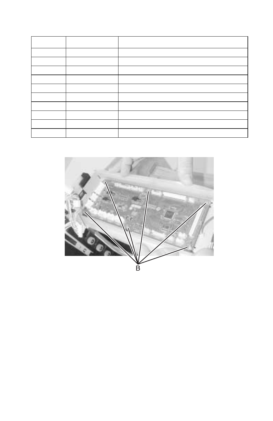
4. Remove six screws (B) from I/O board; remove I/O board.
Note: When reinstalling flat cables, ensure blue side of cable is
opposite pins on connectors DCN1 and DCN3. Flat cable pins are
exposed on only one side (opposite blue side) and must make
contact with metal pins on connectors.
DCN13
12
DCN14
16
DCN15
12
DCN16
14
DCN17
N/A
DCN18
3
DCN19
10
DCN20
3
DCN21
4
DCN22
4
Do not remove the jumper.
Connector Number of pins
Cable wire colors
See also other documents in the category Lexmark Printers:
- E260d (142 pages)
- 6600 Series (173 pages)
- 10N0227 (1 page)
- Z12 (2 pages)
- 301 (144 pages)
- NO. 35 (1 page)
- Z65n (111 pages)
- dn2 (217 pages)
- 10E (144 pages)
- Z2300 (54 pages)
- 230 (213 pages)
- 310 Series (2 pages)
- PRO700 (24 pages)
- C 720 (18 pages)
- C520 (145 pages)
- X656 MFP (104 pages)
- Prospect Pro207 (27 pages)
- 337 (258 pages)
- OptraImage 242 (207 pages)
- T64x (6 pages)
- C524 (146 pages)
- 4098-001 (70 pages)
- 1200 Series (21 pages)
- X650 Series (8 pages)
- 5300 (179 pages)
- 302 (274 pages)
- 4549 (235 pages)
- 202 (320 pages)
- 4076-0XX (89 pages)
- 10N0016 (1 page)
- 5025 (171 pages)
- 1361760 (1 page)
- C 546dtn (6 pages)
- Interpret S400 (40 pages)
- x6575 (2 pages)
- 27S2156-001 (2 pages)
- MENUS AND MESSAGES C522 (55 pages)
- Z35 (101 pages)
- Z25 (24 pages)
- series x5100 (77 pages)
- Z82 (105 pages)
- 2500 Series (76 pages)
- 1200 (208 pages)
- Z33 (114 pages)
- 7600 Series (181 pages)