Troubleshooting & repair, Switch board replacement (continued), Warning – Lincoln Electric INVERTEC SVM129-B User Manual
Page 98
TROUBLESHOOTING & REPAIR
F-60
F-60
INVERTEC® STT® & STT® II
SWITCH BOARD REPLACEMENT (continued)
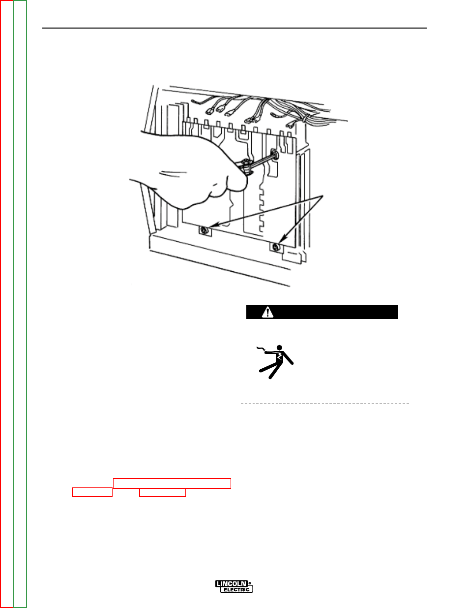
FIGURE F.28 – SWITCH BOARD REMOVAL
PROCEDURE
NOTE: If a test indicates that a switch board is
defective, both switch boards must be
replaced at the same time. In addition to
replacing the switch boards, replace
capacitors C1 and C2 if the following con-
ditions exist:
a. The machine was operating from 380 VAC
or higher when the failure occurred.
b. Burned areas are visible on the switch
boards.
1. Turn off the INVERTEC® STT® & STT® II
and disconnect main AC input power to the
machine.
2. Using the 5/16" nut driver, remove the case
wraparound cover.
3. Perform the Input Filter Capacitor Discharge
Procedure. See the Maintenance section.
ELECTRIC SHOCK can
kill.
• Before continuing with the
test procedure, perform the
capacitor discharge proce-
dure to avoid electric
shock.
4. Carefully disconnect the leads at the top of the
switch board.
5. Using the 3/16" socket wrench, remove the
four cap screws from the switch board. See
Figure F.28.
WARNING
SOCKET
HEAD
SCREWS