Troubleshooting & repair, Warning – Lincoln Electric INVERTEC SVM129-B User Manual
Page 104
TROUBLESHOOTING & REPAIR
F-66
F-66
INVERTEC® STT® & STT® II
CAPACITOR REMOVAL AND REPLACEMENT PROCEDURE (continued)
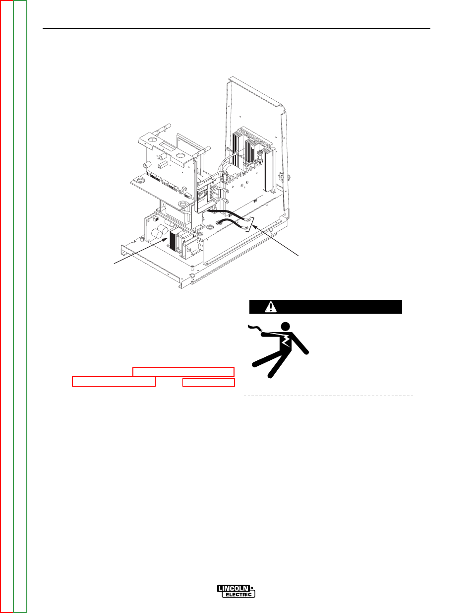
FIGURE F.30 – OUTPUT CHOKE LEAD DISCONNECTION
LOWER
TRAY
AREA
OUTPUT CHOKE/
IGBT MODULE
SPLICED CONNECTION
PROCEDURE
1. Turn off INVERTEC® STT® & STT® II and
disconnect main AC input power to the
machine.
2. Using the 5/16" nut driver, remove the case
wraparound cover.
3. Perform
the
Discharge Procedure. See the Maintenance
section.
ELECTRIC SHOCK can
kill.
• Before continuing with the
test procedure, perform the
capacitor discharge proce-
dure to avoid electric
shock.
4. Locate the lead connection splice from the
output choke to the IGBT module. Remove
the insulating sleeve. Using the 7/16" wrench
disconnect the lead splice. Thread the lower
lead down into the lower tray assembly area.
See Figure F.30.
WARNING