Troubleshooting & repair, T4 auxiliary transformer test (continued) – Lincoln Electric INVERTEC SVM129-B User Manual
Page 59
TROUBLESHOOTING & REPAIR
F-21
F-21
INVERTEC® STT® & STT® II
T4 AUXILIARY TRANSFORMER TEST (continued)
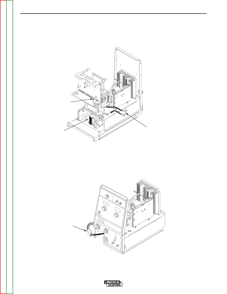
5. Disconnect the current sensing Plug J1 from
the control PC board. Carefully remove Plug
J1 and associated leads from control board
compartment. See Figure F.4.
FIGURE F.4 – PLUG J1 LOCATION
LOWER
TRAY
AREA
OUTPUT CHOKE/
DARLINGTON MODULE
SPLICED CONNECTION
J1 CURRENT
SENSING PLUG
6. Locate and disconnect plug J22 from the
wiring harness. See Figure F.5.
FIGURE F.5 – PLUG J22 LOCATION
PLUG J22