Troubleshooting & repair, Input rectifier test (continued), Ca 9 12 b – Lincoln Electric INVERTEC SVM129-B User Manual
Page 64: Warning
TROUBLESHOOTING & REPAIR
F-26
F-26
INVERTEC® STT® & STT® II
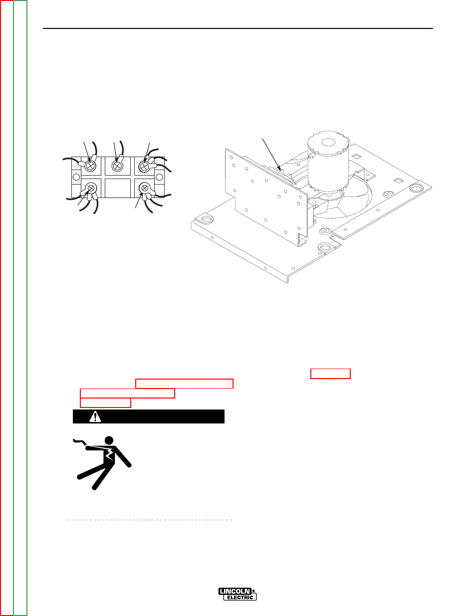
INPUT RECTIFIER TEST (continued)
FIGURE F.9 - INPUT RECTIFIER LOCATION
INPUT
RECTIFIER
C
A
9
12
B
TEST PROCEDURE
1. Turn off the INVERTEC® STT® & STT® II
and disconnect main AC input power to the
machine.
2. Using the 5/16" nut driver, remove the case
wraparound cover.
3. Perform the Input Filter Capacitor
See
the
Maintenance section.
ELECTRIC SHOCK can
kill.
• Before continuing with
the test procedure, per-
form the capacitor dis-
charge procedure to
avoid electric shock.
4. Locate the input rectifier. See Figure F.9.
5. Locate the leads needed to perform the
tests. See Figure F.9.
6. Use an ANALOG ohmmeter to perform the
tests shown in Table F.3.
WARNING