In table f.3, Troubleshooting & repair, Input rectifier test (continued) – Lincoln Electric INVERTEC SVM129-B User Manual
Page 65
6. Replace the input rectifier when any of the
tests are NOT OK.
NOTE: When installing a new input rectifier,
torque the mounting nuts (in a cross-
tightening pattern) to 6 inch-pounds (.7
Nm). Torque terminals to 26 inch-
pounds (3 Nm). PROCEED TO STEP
7 TO CHECK RELATED COMPO-
NENTS.
7. Inspect main power switch S1 and replace
if faulty. Go to step 8.
8. Test capacitors C1 and C2 and replace both
capacitors if either is faulty.
NOTE: Faulty capacitors could be the reason
for input rectifier failure.
Visually inspect the capacitors for leakage,
damage, etc., and use appropriate test equip-
ment to determine component integrity.
9. Perform the Switch Board Test.
10. After all tests are completed, install the
case wraparound cover.
TROUBLESHOOTING & REPAIR
F-27
F-27
INVERTEC® STT® & STT® II
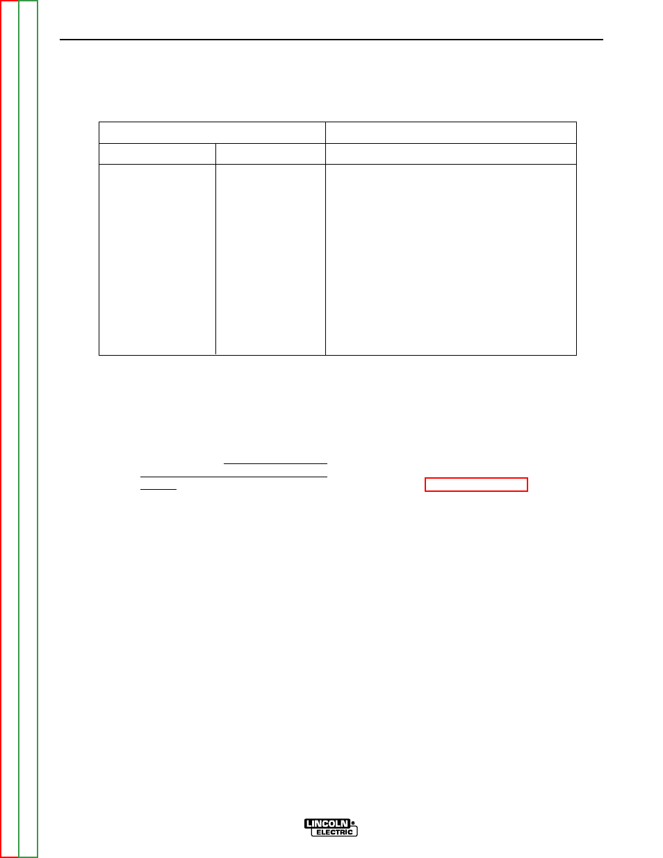
INPUT RECTIFIER TEST (continued)
TABLE F.3 – INPUT RECTIFIER TEST
TEST POINTS
+PROBE
-PROBE
ACCEPTABLE METER READING
9
A
Greater than 100K ohms
9
B
Greater than 100K ohms
9
C
Greater than 100K ohms
A
9
Less than 100 ohms
B
9
Less than 100 ohms
C
9
Less than 100 ohms
12
A
Less than 100 ohms
12
B
Less than 100 ohms
12
C
Less than 100 ohms
A
12
Greater than 100K ohms
B
12
Greater than 100K ohms
C
12
Greater than 100K ohms