Troubleshooting & repair, Power board test (continued) – Lincoln Electric INVERTEC SVM129-B User Manual
Page 82
TROUBLESHOOTING & REPAIR
F-44
F-44
INVERTEC® STT® & STT® II
POWER BOARD TEST (continued)
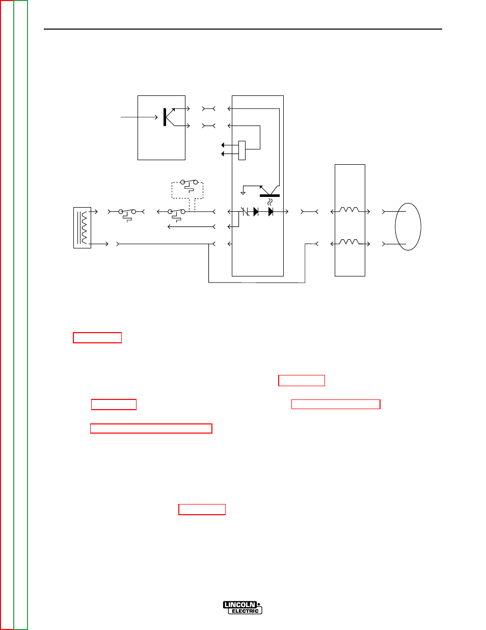
FIGURE F.16 – SIMPLIFIED TRIGGER CIRCUIT
FROM PROTECTION
BOARD OVERVOLTAGE
PWM
OUTPUTS
TO POWER
BOARD
7J6
2J6
11J4
3J4
13J36
5J36
8J33
6J34
9J4
12J4
3J31
6J22
6J4
POWER BOARD
CONTROL BOARD
REMOTE
PROTECTION
BOARD
14 AMPHENOL
#301
#305
#503A
#224
#210
#212
#223
#212C
#413
#405
C
D
T1 AUXILIARY
TRANSFORMER
2
4
V
A
C
P
W
M
5J4
TO
POWER
BOARD
2J31
3.5 ohms
3.5 ohms
STT II Only
#379
7. Carefully test for 15VDC output from the
power PC board at plug J6 pin1 (lead #275)
(-) and plug J6 pin 6 (lead #302)(+). See
Figure F.15.
NOTE: If the 18VAC is present but the 15VDC is
NOT, the power PC board may be faulty.
8. Carefully test for 24VAC input from the T1
Auxiliary Transformer between plug J6 pin 4
(lead#211A) and plug J6 pin 9 (lead#212A).
See Figure F.15.
NOTE: If the 24VAC is NOT present, perform the
T1 Auxiliary Transformer Test.
Also
check the associated wiring. See the
Wiring Diagram. The control PC board or
thermostats may be faulty. See Figure
F.16, the Simplified Trigger Circuit dia-
gram.
9. Carefully test for 24VDC at the power PC
board at plug J7 pin 2 (lead #309)(+) to plug
J14 pin2 (lead #313)(-). See Figure F.15.
NOTE: If the 24VAC is present but the 24VDC is
NOT, the power PC board may be faulty.
10. Carefully test for approximately 24VDC at
plug J7 pin 2 (lead#309)(+) to plug J7 pin 4
(lead#310)(-). If the 24VDC is NOT present,
test for approximately 1VDC at plug J14 pin1
(lead#311)(+) to plug J14 pin 2 (lead#313)(-).
See Figure F.15.
NOTE: If more than 1VDC is measured, perform
NOTE: If approximately 1VDC IS present and
the 24VDC is NOT present at leads
#309 to #310, the power PC board may
be faulty.
11. After all tests are completed, install the front
panel assembly.
12. Install the case wraparound cover.