Troubleshooting & repair, Warning – Lincoln Electric INVERTEC SVM129-B User Manual
Page 112
TROUBLESHOOTING & REPAIR
F-74
F-74
INVERTEC® STT® & STT® II
OUTPUT RECTIFIER REMOVAL AND REPLACEMENT (continued)
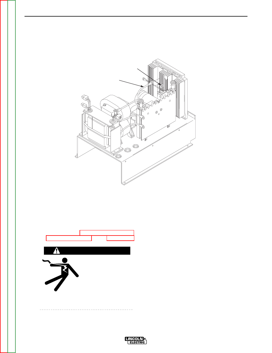
FIGURE F.39 – CHOKE LEAD/HEAT SINK CONNECTION
CHOKE LEAD
HEAT SINK TAB
PROCEDURE
1. Turn off INVERTEC® STT® & STT® II and
disconnect main AC input power to the
machine.
2. Using the 5/16" nut driver, remove the case
wraparound cover.
3. Perform the Input Filter Capacitor
Discharge Procedure. See the Maintenance
section.
ELECTRIC SHOCK can
kill.
• Before continuing with
the test procedure, per-
form the capacitor dis-
charge procedure to
avoid electric shock.
4. Using the slot head screw driver, loosen the
input cable strain relief.
5. Using the 5/16" nut driver, remove the four
screws securing the case back to the inter-
nal horizontal baffles.
6. Carefully pull the case back away from the
output rectifier assembly.
NOTE: The case back will NOT detach from
the case bottom.
7. Using the 7/16" wrench, remove the four
bolts and washers mounting the fan motor
bracket to the top horizontal baffle.
Carefully set the fan and motor assembly
aside. Note insulation placement for
reassembly.
NOTE: The fan motor leads do NOT have to
be cut.
8. Using the 7/16" wrench, remove the choke
lead from the heat sink tab. See Figure
F.39.
WARNING