3 setting the digital output dip switches, Setting the digital output dip switches, Table 10 – Liebert Universal Monitor User Manual
Page 36: Table 11, Setting the digital output dip, Switches
Wiring and Connections - Optional Expansion Board
28
5.2.3 Setting the Digital Output DIP Switches
Each digital output on the optional Expansion Board has an associated DIP switch that can deter-
mine its operation in the event of loss of communication with the Universal Monitor or loss of power.
When the Universal Monitor calls for an Expansion Board output to be ON, it sends a command to the
Expansion Board to turn the output to the ON state; this is signified by the output LED being ON.
The behavior of the output when it is ON is determined by the position of the DIP switch.
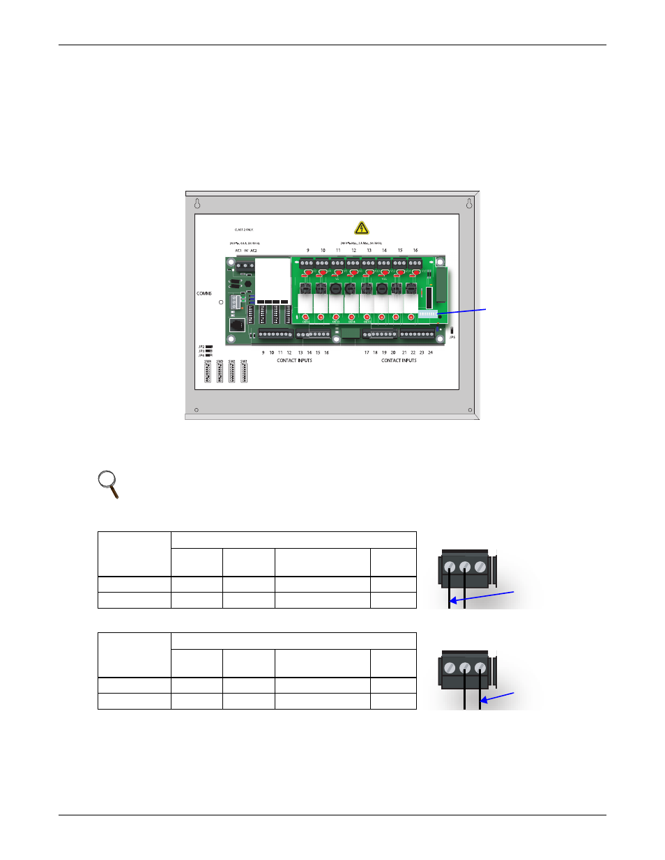
The DIP switches for the outputs are on a switch bank on the right side of the Expansion Board, as
shown below. Each switch corresponds to an output on the board in order from left to right—for exam-
ple, DIP switch 1 corresponds to Output 9; DIP switch 2 corresponds to Output 10.
Tables 10 and 11 show how to set the DIP switch for each output based on how the output is wired
(see 5.2.2 - Connecting Digital Outputs) and how you want it to perform during normal operation,
when communication with the Universal Monitor is lost or when power fails.
The Expansion Board comes from the factory with all digital output DIP switches in the OFF position
(normally open). The DIP switch setting for each digital output can be changed to ON (normally closed).
To change the state of any output to the factory default of NO (Normally Open) or to NC (Normally
Closed), move each switch to the appropriate position:
• Move the switch down to the OFF position for NO (Normally Open)—the default setting.
• Move the switch up to the ON position for NC (Normally Closed).
NOTE
After a loss of communications with the Universal Monitor, there is a time delay—about five
minutes—before the Expansion Board changes the state of an output.
Table 10
DIP switch setting - outputs wired as Normally Closed (N.C.)
If Output
DIP Switch
is:
State of Output When:
Light is
ON
Light is
OFF
Communication
with UM is Lost
Power
Fails
Up (ON)
Closed
Open
Closed
Closed
Down (OFF)
Open
Closed
Closed
Closed
Table 11
DIP switch setting - outputs wired as Normally Open (N.O.)
If Output
DIP Switch
is:
State of Output When:
Light is
ON
Light is
OFF
Communication
with UM is Lost
Power
Fails
Up (ON)
Open
Closed
Open
Open
Down (OFF)
Closed
Open
Open
Open
OUT1
K1
V1
V3
V5
V7
V9
V11
V13
V15
V2
V4
V6
V8
V10
V12
V14
V16
K2
K3
K4
K5
K6
K7
K8
OUT2
OUT3
OUT4
OUT5
OUT6
OUT7
OUT8
S4
S3
S2
S1
Multiflex 168AO
810-3065
DEFAULT SETTINGS FOR USE WITH UNIVERSAL MONITOR
USE COPPER (CU) CONDUCTORS ONLY.
D6
POWER INPUT
EIA485 + (to UM-)
0V
EIA485 - (to UM+)
RELAY OUTPUTS
Digital output
DIP switches
Optional
Expansion
Board
N.C.
N.O.
Wire connected
to N.C. terminal
N.C.
N.O.
Wire connected
to N.O. terminal