7 controller board overview, Table 1 controller board components, Controller board overview – Liebert Universal Monitor User Manual
Page 12: Controller board components
Introduction
4
1.7
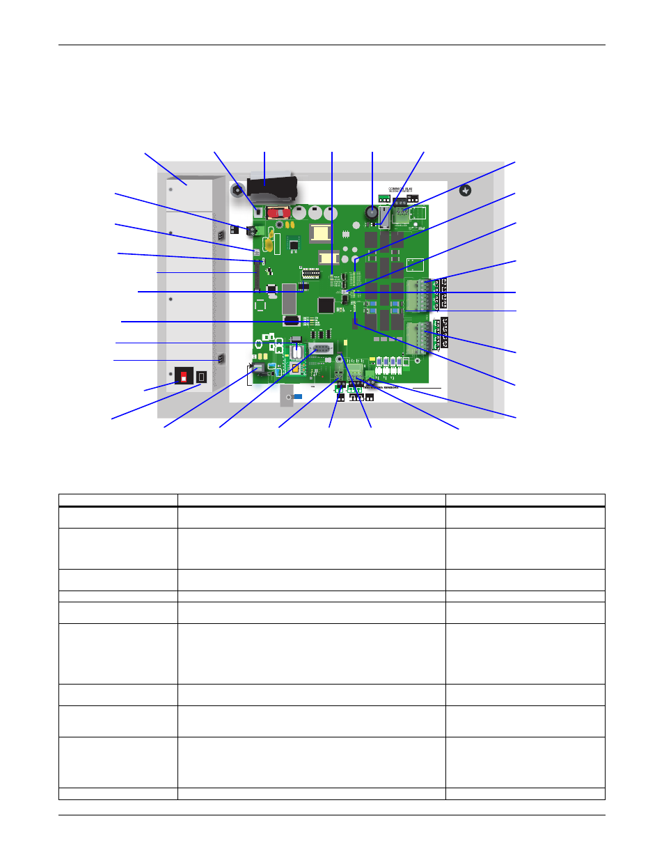
Controller Board Overview
The Universal Monitor’s controller board has connectors for eight digital inputs, four analog inputs
and eight digital outputs, as shown below. The board comes complete with light emitting diodes
(LEDs) to display the status of monitored devices, a battery pack for short-term backup, communica-
tions ports, power connections and other features necessary to monitor and protect your operation.
Table 1
Controller board components
Item
Description
For more information, see:
A - Power On/Off
switch
Power switch for the controller board. When switched off,
the battery pack is disabled.
B - Battery pack
Provides battery backup during a power loss to maintain
normal operation of the panel for a minimum of 10 minutes.
The analog inputs will not be functional during a power loss
(P/N 133455P1).
2.4.3: Connecting the Battery Pack
Indicates the connection status between the Universal
Monitor and SiteScan Web.
D - Audible horn
Provides audible notification when an alarm occurs.
N/A
Jumper to disable the audible horn (factory default is
enabled).
N/A
F - Common Alarm
connectors
The two common alarm connections are used to connect to
a secondary warning device such as a horn, light or
Building Management System (BMS). When an alarm is
present, the contacts close and the external warning device
is activated/notified. The common alarm contacts may be
configured to be reset with the Silence button/command.
G - Digital output
status LEDs
Each output has an LED to indicate its status: ON/OFF
(energized/de-energized).
H - Manual Override
Switch (outputs)
Placing the switch in the ON position will turn ON, or energize,
all eight outputs simultaneously. This switch removes all
automatic output control from the Universal Monitor.
I - Digital output
connectors
Each of the eight output connections is a two-state point:
ON/OFF (energized/de-energized).
An example of a field digital output point is a motor starter.
4.2.2: Connecting Digital Outputs
J - Status LEDs
Indicates the operational status of the controller board.
BAR CODEBA
R C
OD
E
LIEBERT
BATTERY
LCD
CONTRAST
VBATT
START
TB7:
24V INPUT
P23:
BATTERY
485
+
—
+
—
(TOP)
(BOTTOM)
TB10: COMMS
422
TB3:
RELAY
OUTPUTS
TB2:
CONTACT
INPUTS
ASS
REV
ONON
PFM5
OFF
ON
PFM2
OFF
(BOTTOM)
(TOP)
4
3
2
1
8
7
6
5
(BOTTOM)
(TOP)
4
3
2
1
8
7
6
5
J11: PHONE
PIN 3-TIP
PIN 4-RING
MODEM
TB5: COMMON ALARM
(TERMINAL BLOCKS ROTATED IN VIEW)
(BOTTOM)
OM
OM
Q11
R2
R40
P11
+
LS1
TOP
ENABLE
AUDIBLE
(TOP)
NO C NC
NO C NC
ALL CIRCUITS:
CLASS 2
TB9: ANALOG
GROUND
AG
+
+
—
—
+
—
+
—
3-4 BOTTOM
1-2 TOP
ON
MODEM
4
D
CAN TX
CAN RX
DS83
DS84
1
ON
ON
TP1
GND
S2
OFF
DIP
2 3 4 5 6 7 8
OUTPUT1
DS56
DS54
DS63
DS61
DS60
DS62
DS55
DS57
DS59
DS58
DS53
MOP
F PROG
574 TX
574 RX
485 RX
485 TX
OUTPUT2
OUTPUT3
OUTPUT4
OUTPUT5
OUTPUT6
OUTPUT7
OUTPUT8
CTRLLOCK
SENLOCK
CMN ALR
INPUT1
DS70
DS67
DS66
DS65
DS64
R334
INPUT2
INPUT3
INPUT4
INPUT5
INPUT6
INPUT7
INPUT8
C71
R
4
I - Digital output
connectors
L - Digital input
connectors
T - Phone
line
connector
R - EIA485
connector
S - Serial
interface
connector
(RS232/EIA574)
CC - Battery pack
connector
DD - 24VAC power
connector
EE - Transformer
Module
E - Audible horn
jumper
G - Digital output
status LEDs
K - Digital output
loss-of-power
jumper
H - Manual
Override Switch
(outputs)
X - Modem
J - Status LEDs
B - Battery
pack
A - Power
On/Off switch
AA - LCD connector
N - Analog
ground
connector
O - Analog
input
connectors
U - Power
receptacle
V - Power On/Off
switch
M - Digital input
status LEDs
BB - LCD contrast
adjustment
C - EIA422
LEDs
Y - Modem
status LEDs
P - 12VDC/24VDC
analog input
jumper
Q - SiteScan
Web
connector
(EIA422)
D - Audible
horn
Z - DIP switch 1
W - 24VAC
connector
F - Common
Alarm
connectors