Efault, Ettings, Uick – Liebert Universal Monitor User Manual
Page 140: Eference, Uide, Table 37, B - d
Default Settings Quick Reference Guide
132
A
PPENDIX
B - D
EFAULT
S
ETTINGS
Q
UICK
R
EFERENCE
G
UIDE
This appendix provides a quick reference to default settings for the Universal Monitor and the
optional Expansion Board. These settings also appear throughout the manual.
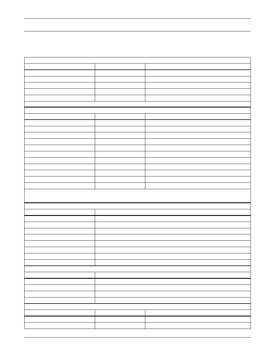
Table 37
Universal Monitor - default settings for inputs and outputs
DEFAULT SETTINGS - DIGITAL INPUTS (FROM TABLE 21)
Feature
Default
Other Options
LABEL
INPUT_01 - INPUT_08
Any name (up to eight characters)
NORM OPEN/CLOSE
NO (Normally open)
NC (Normally closed)
ALARM/EVENT
AL (Alarmable)
EV (Event)
LATCHED
NL (Unlatched) / N (No)*
L (Latched) / Y (Yes)*
DELAY
00:01 (1 second)
Any time (in minutes and seconds) from 00:00 to 99:59
* NOTE: Different abbreviations are used to designate a digital input as Latched or Unlatched.
DEFAULT SETTINGS - ANALOG SENSOR INPUTS (FROM TABLE 22)
Feature
Default
Other Options
CONNECTED*
N (Not connected)*
Y (Connected)**
LABEL
SENSOR_1 - SENSOR_4 Any name (up to eight characters)
UNITS
Blank
Any units (up to three characters)
4 mA
-999.9
Can define up to two decimal places—e.g., -99.99
20 mA
+999.9
Can define up to two decimal places—e.g., +99.99
OFFSET
+000.0
Can define up to two decimal places—e.g., +00.00
ALARM/EVENT
AL (Alarmable)
EV (Event)
LATCHED
N (Unlatched)
Y (Latched)
LOW SETPT
-0999.9
Can define up to two decimal places—e.g., -999.99
HIGH SETPT
+0999.9
Can define up to two decimal places—e.g., +999.99
SENSOR DELAY
00:01 (1 second)
Any time (in minutes and seconds) from 00:00 to 99:59
* If a sensor is configured as N (Not connected), the display will show an empty reading (blank spaces).
** If a sensor is configured as Y (Connected) and is functioning properly, the display will show a reading.
If the connected sensor is not functioning properly, the display will show dashes (------) indicating a problem.
DEFAULT MAPPING OF DIGITAL INPUTS TO DIGITAL OUTPUTS (FROM TABLE 23)
Digital input
By default, mapped to digital output:
Input_01
Output01
Input_02
Output02
Input_03
Output03
Input_04
Output04
Input_05
Output05
Input_06
Output06
Input_07
Output07
Input_08
Output08
DEFAULT MAPPING OF ANALOG INPUTS TO DIGITAL OUTPUTS (FROM TABLE 24)
Analog input
By default, mapped to digital output:
Sensor_1
(none)
Sensor_2
(none)
Sensor_3
(none)
Sensor_4
(none)
DEFAULT SETTINGS - DIGITAL OUTPUTS (FROM TABLE 25)
Feature
Default
Other Options
LABEL
OUTPUT01 - OUTPUT08
Any name (up to eight characters)
NORM OPEN/CLOSE
NO (Normally open)
NC (Normally closed)