8 optional expansion board overview, Table 2 expansion board components, Optional expansion board overview – Liebert Universal Monitor User Manual
Page 14: Table 2, Expansion board components
Introduction
6
1.8
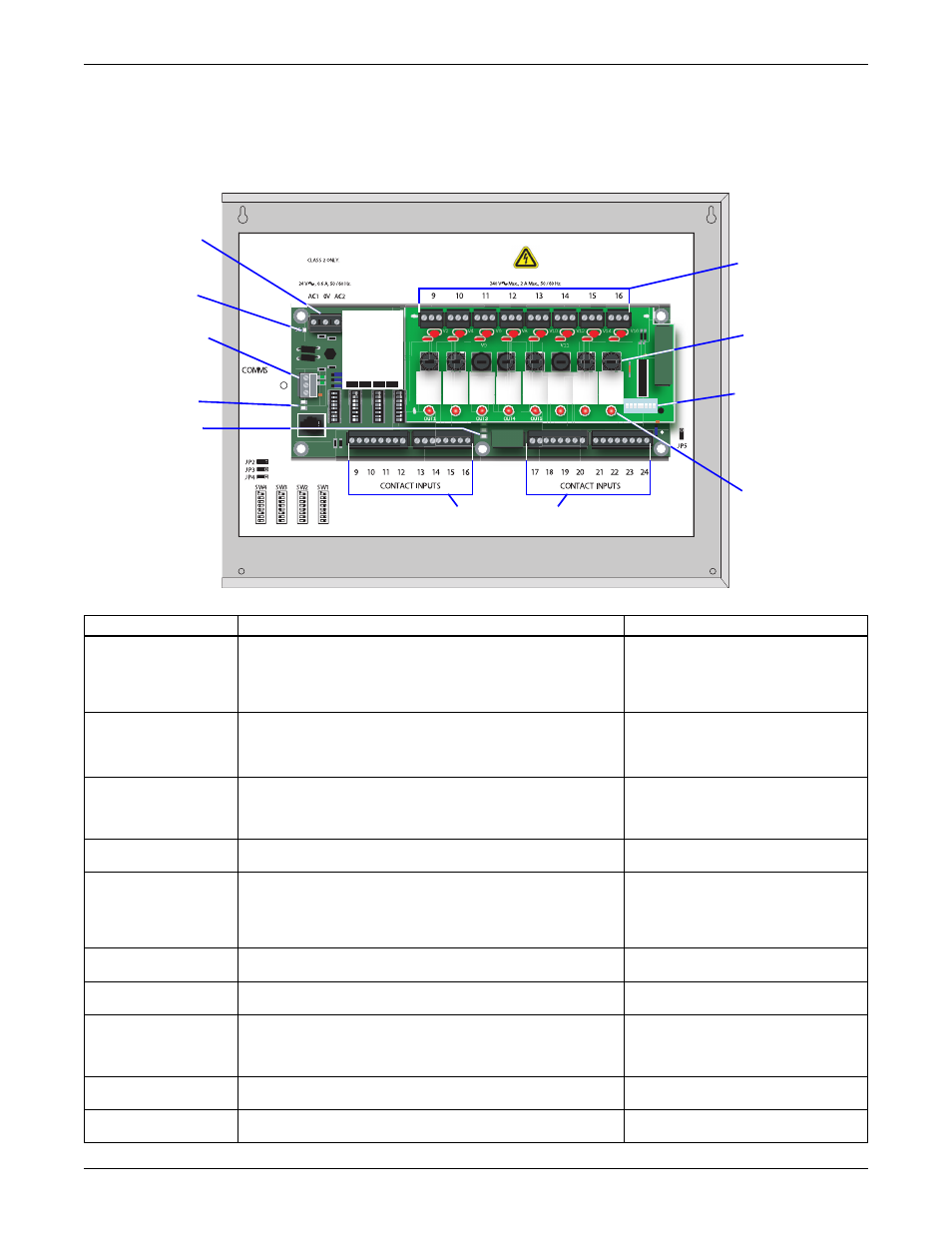
Optional Expansion Board Overview
The Universal Monitor Expansion Board, purchased separately, has connectors for 16 digital inputs
and eight digital outputs, as shown below. The board has light emitting diodes (LEDs) to display the
status of monitored output devices, communications ports for connection to the Universal Monitor,
power connections and other features necessary to monitor and protect your operation.
Table 2
Expansion board components
Item
Description
For more information, see:
A - Digital output
connectors (8)
Each of the eight output connections is a two-state point:
ON/OFF (energized/de-energized).
An example of a field digital output point is a motor starter.
4.2.2: Connecting Digital Outputs
B - Digital output
fuses (8)
Bussmann GMA-2 or equivalent. 250V 2A Fast Blow fuse.
CAUTION: Fuses must be replaced with equivalent fuses.
NOTE: Two (2) replacement fuses are shipped with
the Expansion Board enclosure.
N/A
C - Digital output
DIP switch
DIP switch used for setting Normally Open / Normally
Closed.
5.2.3: Setting the Digital Output DIP
9.7.3: Set Expansion Board Output by
D - Digital output
status LEDs (8)
Each output has an LED to indicate its status: ON/OFF
(energized/de-energized).
1.10: LED Indicators - Optional
E - Digital input
connectors (16)
Each of the 16 input connections is a two-state point: ON/
OFF (energized/de-energized).
An example of a field digital input point is a leak detector.
4.2.1: Connecting Digital Inputs
F - General status
LED (green)
Indicates the operational status of the Expansion Board.
1.10: LED Indicators - Optional
G - EIA485 status
LEDs (yellow & red)
Two LEDs indicate status of the EIA485 connection:
ON/OFF (energized/de-energized).
1.10: LED Indicators - Optional
H - EIA485
connector
Connection to the Universal Monitor.
5.3.1: Connect EIA485 Connectors to
9.10: Setup Exp Board - Optional
I - Power status LED
(green)
Indicates the power status of the Expansion Board.
1.10: LED Indicators - Optional
J - 24VAC power
connector
Power connection for the Expansion Board. Requires
24VAC.
OUT1
K1
V1
V3
V5
V7
V9
V11
V13
V15
V2
V4
V6
V8
V10
V12
V14
V16
K2
K3
K4
K5
K6
K7
K8
OUT2
OUT3
OUT4
OUT5
OUT6
OUT7
OUT8
S4
S3
S2
S1
Multiflex 168AO
810-3065
DEFAULT SETTINGS FOR USE WITH UNIVERSAL MONITOR
USE COPPER (CU) CONDUCTORS ONLY.
D6
POWER INPUT
EIA485 + (to UM-)
0V
EIA485 - (to UM+)
RELAY OUTPUTS
H - EIA485
connector
E - Digital input
connectors (16)
F - General
status LED
(green)
G - EIA485
status LEDs
(yellow & red)
I - Power status
LED (green)
B - Digital
output
fuses (8)
J - 24VAC
power
connector
A - Digital output
connectors (8)
C - Digital
output
DIP switch
D - Digital output
status LEDs (8)