Connections, Chapter one : connecting your devices, Only for some areas) – Kenwood KRF-X7775D User Manual
Page 96: Speaker wire binding post, Channel space/fm de- emphasis switch
2
Chapter One : Connecting Your Devices
Connections
OPTICAL
CD1
DVD
DVD
VIDEO
2
VIDEO
3
DIGITAL IN
COAXIAL
DIGITAL OUT
VIDEO
3 IN
COMPONENT VIDEO
DVD
IN
MONITOR
OUT
MONITOR
OUT
PLAY
IN
PLAY
IN
PLAY
IN
REC
OUT
REC
OUT
PLAY
IN
S VIDEO
VIDEO
PRE OUT
ZONE B PRE OUT
R
L
AUDIO
R
L
FRONT
R
L
SURROUND
R
L
R
L
SURROUND BACK
SUB WOOFER CENTER
VIDEO
R
L
B
A
AUDIO
VIDEO1
VIDEO2
VIDEO3
DVD FRONT
DVD/
6CH.
INPUT
SURROUND
CENTER
SUBWOOFER
PHONO
CD1
REC
OUT
PLAY
IN
MD/
TAPE1
REC
OUT
PLAY
IN
CD-R
REC
OUT
PLAY
IN
CD2/
TAPE2
MONITOR
CENTER
SPEAKER
(6–16
Ω
)
SURROUND
SPEAKERS
(6–16
Ω
)
AC 120V 60Hz
SWITCHED TOTAL
90W 0.75A MAX.
FRONT SPEAKERS
(6–16
Ω
)
ANTENNA
GND
AM
FM 75
Ω
SYSTEM
CONTROL
SL16 TEXT
REMOTE
IR OUT
LCD
REMOTE
IR RECEIVER
IN
IR RECEIVER
IN
DVD CONTROL
C
R
L
R
L
A
B
DC12V 20mA
DC12V
20mA
AC 220 —
240V
AC 110 —
120V
50
µ
s
AM 9kHz
FM 50kHz
75
µ
s
AM 10kHz
FM 100kHz
DE-EMPHASIS
CHANNEL SPACE
Y
C
B
C
R
Y
C
B
C
R
Y
C
B
C
R
IR OUT
LCD
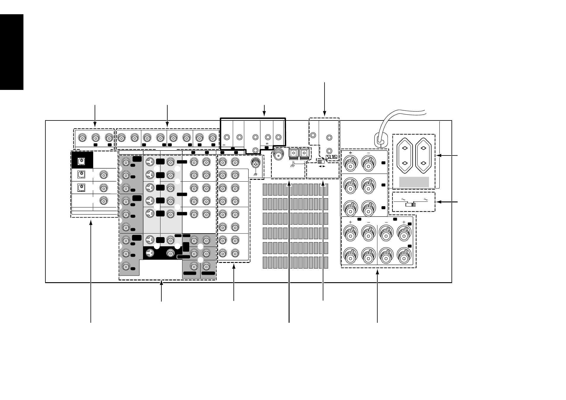
Zone B pre out jacks
Audio component jacks
Pre out jacks
Antenna jacks
Supplemental infrared receiver
and sensor jacks (for U.K. and
U.S. military)
System control jacks
The following diagram shows the entire back of the KRF-X7775D.
Digital jacks
(coaxial and optical)
Video component jacks
AC voltage
selector switch
(only for some
areas)
The shape of plugs
are different
between countries
Channel space/FM de-
emphasis switch
(only for some areas)
Note that some component jacks are linked to specific
digital jacks. For example, if you connect a video compo-
nent with a digital optical cable, you should connect the
analog cables to the VIDEO2 video component jacks and
the digital cable to the VIDEO2 digital optical jack.
Speaker wire
binding post