Kyocera FS-1700 User Manual
Page 144
C.2. RS-232C/RS-422A Interface
C-8
Verifying the Setting
The procedure described below should be followed to verify that the RS-422A mode had been cor-
rectly set. Print the service status page to verify that the RS-422A mode has been correctly set.
1. Make sure the power switch is off. Plug the power cord into the printer and turn power on.
2. If the printer is on-line, select
in the Mode Select menu (refer
to Mode Select Menu at the end of this document), and print the service status page.
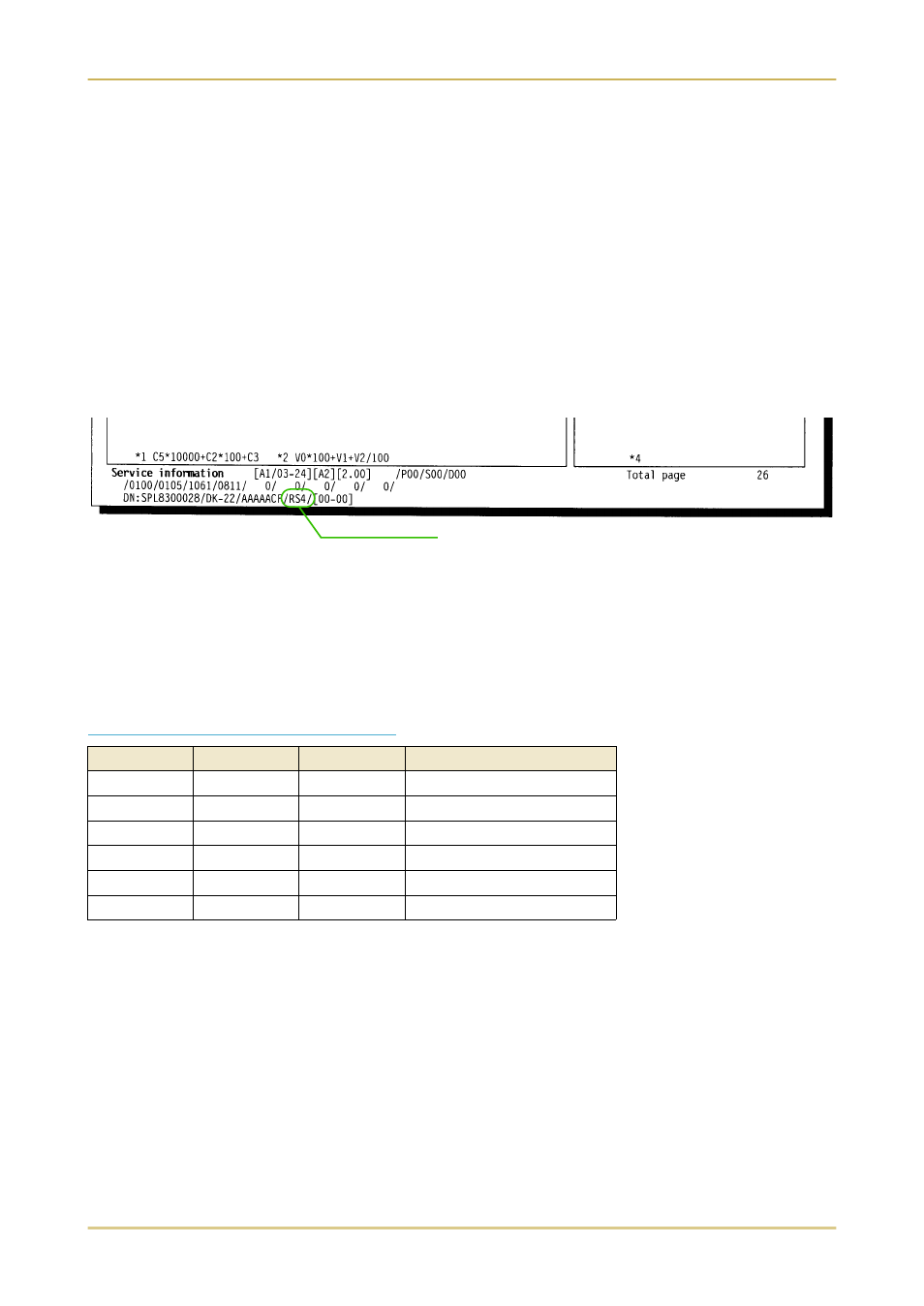
3. Verify whether the setting is correct by checking the status printed at the bottom of the page.
The following sample indicates that "RS-422A" is set "RS4". If "RS-232C" is set, "RS2" appears.
Interface Signals
The pins in the printer's RS-422A interface connector carry the signals listed in Table C.3.
Overview of Signals (RS-422A)
FG - Frame Ground - (Pin 1)
This pin is connected directly to the printer frame.
SG - Signal Ground - (Pin 7)
All signals can transmit between the printer and the host computer to send each signals with a
signal ground.
Table C.3. RS-422A Signal Pin Assignments
Pin
In/out
Signal
Description
1
–
FG
Frame ground
3
In
RDA
Receive data Inverted
7
–
SG
Signal ground
9
Out
SDA
Send data Inverted
10
Out
SDB
Send data
18
In
RDB
Receive data
[Printer Status Page]
Indicates the current serial
interface mode.