15 fan headers, Serial ports, Universal serial bus headers – SUPER MICRO Computer 5015M-U User Manual
Page 49
Chapter 5: Advanced Serverboard Setup
5-15
Fan Headers
The PDSMU has six fan headers, des-
ignated Fan1 through Fan6. All are
4-pin fans to provide a Pulse Width
Modulated (PWM) signal, however
pins 1-3 of the headers are backward
compatible with traditional 3-pin fans.
Connect the CPU heatsink fan and
the system (chassis) fans to these
headers. Their speed is controlled via
Thermal Management with a BIOS
setting. See the tables on the right
for pin defi nitions.
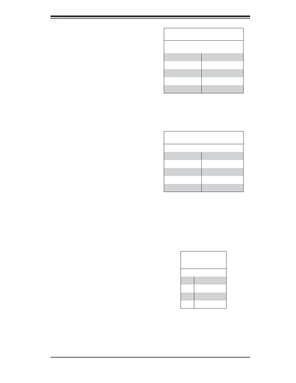
Serial Ports
The COM1 serial port is located on
the IO backplane. COM2 is a header
on the serverboard (see serverboard
layout for location). See the table on
the right for pin defi nitions.
Note: Pin 10 is included on the header but not on
the port. NC indicates no connection.
Serial Port Pin Defi nitions
(COM1, COM2)
Pin # Defi nition
Pin # Defi nition
1
DCD
6
DSR
2
RXD
7
RTS
3
TXD
8
CTS
4
DTR
9
RI
5
Ground
10
NC
Fan Header
Pin Defi nitions
(FAN1-6)
Pin# Defi nition
1
Ground (Black)
2
+12V (Red)
3
Tachometer
4
PWM Control
Universal Serial Bus
Headers
Four additional USB headers (USB2/3
and USB4/5) are included on the
serverboard. These may be used for
front side access. A USB cable (not
included) is needed for the connec-
tion. See the table on the right for
pin defi nitions.
Universal Serial Bus Headers
Pin Defi nitions (USB2/3, USB4/5)
USB2
Pin # Defi nition
USB3, USB4
Pin # Defi nition
1
+5V
1
+5V
2
PO-
2
PO-
3
PO+
3
PO+
4
Ground
4
Ground
5
Key
5
NC
Note: When using Thermal Management set-
tings, please use all 3-pin fans or all 4-pin fans.
Please do not use both 3-pin fans and 4-pin fans
together.