SMC Networks 486DX4 User Manual
Page 38
AR-B1462 User¡
¦s Guide
4-2
4.2 LCD FLAT PANEL DISPLAY
This section describes the configuration and installation procedure for a LCD display. Skip this section if you are
using a CRT monitor only.
Use the Flash memory Writer utility to download the new BIOS file into the ROM chip to configure the BIOS default
settings for different types of LCD panels. Next, set your system properly and configure the AR-B1462 VGA
module for the right type of LCD panel you are using.
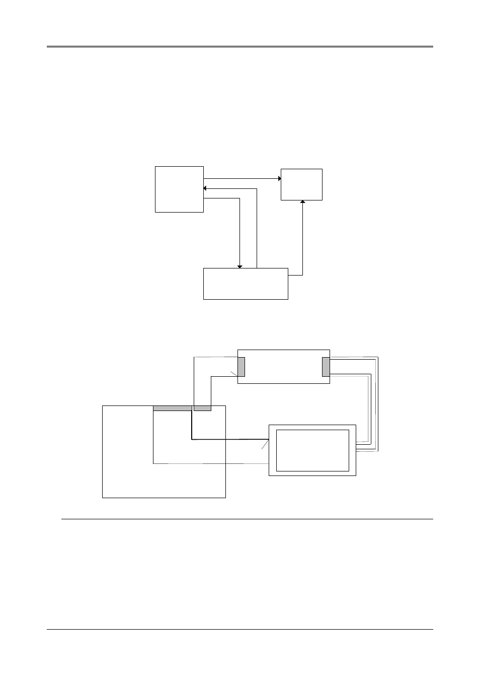
The following shows the block diagram of the system when using the AR-B1462 with a LCD display.
AR-B1462
CPU Boad
LCD
Panel
Inverter
Board
VBL Control
+12V, +5V
VEE
FL HIGH
Voltage
Figure 4-2 LCD Panel Block Diagram
The block diagram shows that the AR-B1462 still needs components to use with a LCD panel. The inverter board
provides the control for the brightness and the contrast of the LCD panel. The inverter is also the components that
supply the high voltage to drive the LCD panel. Each item will be explained further in the section.
Pin 1
AR-B1462
CPU Board
Pin 1
CN14
LCD
Panel
Inverter & Contrast
J10
Figure 4-3 LCD Panel Cable Installation Diagram
NOTE: Be careful with the pin orientation when installing connectors and the cables. A wrong connection can easily
destroy your LCD panel. Pin 1 of the cable connector is indicated with a sticker and pin1 of the ribbon
cable is usually has a different color.