Crt/lcd flat panel display, 1 connecting the crt monitor, 1 crt connector (cn13) – SMC Networks 486DX4 User Manual
Page 37
AR-B1462 User¡
¦s Guide
4-1
4. CRT/LCD FLAT PANEL DISPLAY
This section describes the configuration and installation procedure using LCD and CRT display.
l Connecting the CRT Monitor
l LCD Flat Panel Display
l Supported LCD Panel
4.1 CONNECTING THE CRT MONITOR
To connect a CRT monitor, an adapter cable has to be connected to the CN13 (10-pin header type) connector.
This adapter cable is included in your AR-B1462 package.
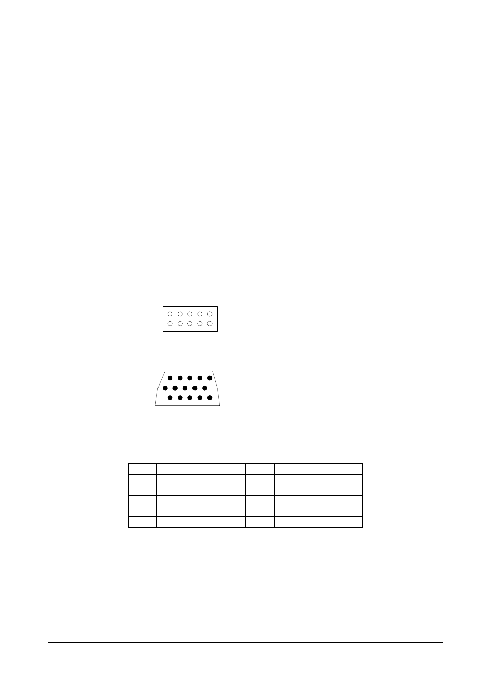
4.1.1 CRT Connector (CN13)
The AR-B1462 support CRT color monitors. AR-B1462 used onboard VGA chipset and supported 1MB on-board
VRAM, and the AR-B1462A supported 2MB on-board VRAM. For different VGA display modes, your monitor must
possess certain characteristics to display the mode you want.
To connect to a CRT monitor, an adapter cable has to be connected to the CN13 connector. CN13 is used to
connect with a VGA monitor when you are using the on-board VGA controller as a display adapter.
CN13 is a 10-pin connector that attaches to the CRT monitor via a HD-sub 15-pin adapter cable. Pin assignments
for the CN13 & HDB15 connector is as follows:
1
3
5
7
9
2
4
6
8
10
1 RED
2 GND
3 GREEN
5 BLUE
7 VSYNC
9 HSYNC
4 AGND
6 AGND
8 AGND
10 GND
1 Red
2 Green
3 Blue
13 Horizontial Sync
14 Vertical Sync
4, 9, 11, 12, & 15 Not used
5 & 10 Ground
6, 7 & 8 AGND
1
3
5
7
9
2
4
6
8
10
15
14
13
12
11
Figure 4-1 CN13: CRT Connector
CN13
DB-15
FUNCTION
CN13
DB-15
FUNCTION
1
1
Red
2
5
GND
3
2
Green
4
6
AGND
5
3
Blue
6
7
AGND
7
14
V-sync
8
8
AGND
9
13
H-sync
10
10
GND
Table 4-1 CRT Connector Assignment