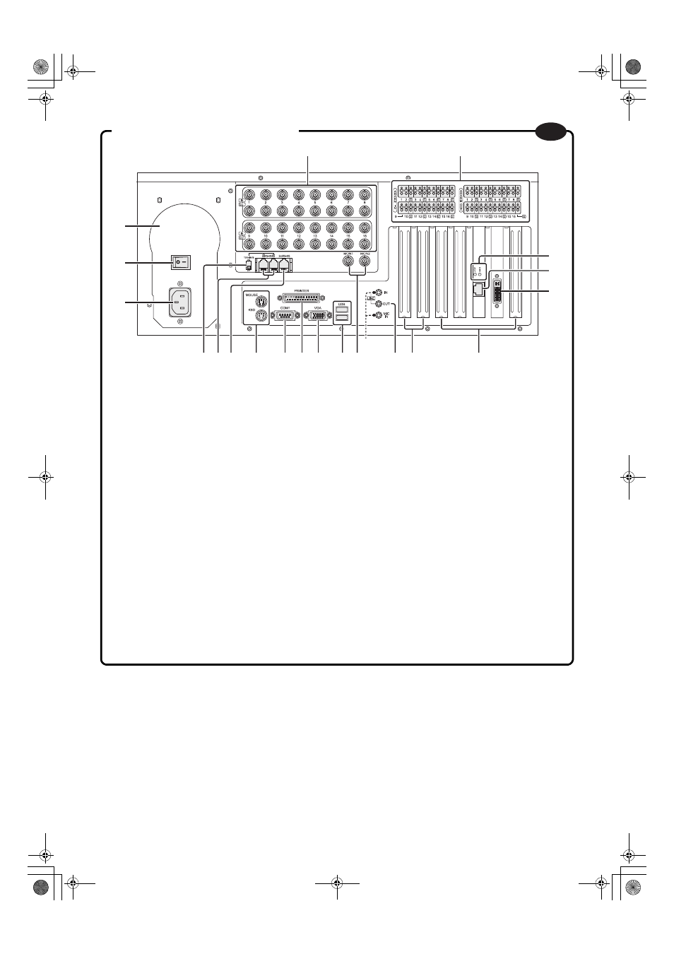
Names of parts (rear panel) – Sanyo DSR-HB8000 User Manual
Page 6
- 5 -
T
1
2
(
✱)
6 7 8
9
I
K
F
H
G
L
J
M
P
O
N
4
3
5
1
IN/OUT terminals (video input/output)
2
ALARM IN/OUT terminals (alarm input/output)
3
Air duct
4
Standby switch
5
Power socket
6
RS-485 TERMINATE ON/OFF switch
7
RS-485 A/B port
• To connect a Sanyo system controller, Sanyo PTZ
camera, etc.
8
2nd RS-485 port
• To connect a competitor’s PTZ camera, etc.
A Sanyo camera cannot be connected.
9
MOUSE/KBD terminal (mouse/keyboard)
F
COM1 serial port
• To connect expansion equipment, such as modems,
ATM, POS, etc.
G
PRINTER port (printer)
H
VGA port (monitor)
I
USB terminal
J
MON1/MON2 terminal (video output; analog)
• MON1: Multi-screen or single-screen
• MON2: Single-screen
K
LINE OUT terminal (audio output; mono)
L
PCI Express slot (for expansion)
M
PCI bus slot (for expansion)
N
LINK/ACT indicator
• LINK: On when connected to the network hub.
• ACT: Blinks when accessing the network.
O
LAN port (network)
P
Audio conversion port (audio input; mono)
• Can input the audio of the 16 channels of the
camera.
*) The LINE IN/MIC IN terminals are exclusively for
service.
Names of parts (rear panel)
GB
L8HBR_WA(DSR-HB8000_install).book 5 ページ 2007年4月5日 木曜日 午後7時13分