Front panel of the timeprovider 1000, Rear panel of the timeprovider 1100 – old version, Figure 1-4 – Symmetricom EDGE CLOCK 1000 User Manual
Page 29
097-58001-02 Revision G – April 2008
TimeProvider User’s Guide
29
Chapter 1 Overview of the TimeProvider
Physical Description
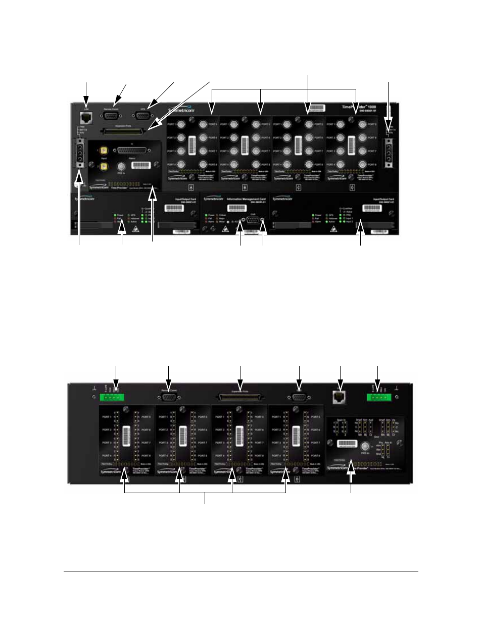
Figure 1-4.
Front Panel of the TimeProvider 1000
illustrates the location of the connectors, cards, and modules on the rear
panel of the TimeProvider 1100. The chassis in
uses a 3-pin power connector.
Figure 1-5.
Rear Panel of the TimeProvider 1100 – Old Version
Ethernet
Output Modules
IOC 2
IOC 1
IMC
Power
Connector
Power
Connector
Connector
Local Craft
Connector
Remote Serial
Connector
Expansion
Connector
GPS
Connector
Input
Module
Ethernet
Output Modules
Power
Connector
Power
Connector
Input
Connector
Remote Serial
Connector
Expansion
Connector
GPS
Module
Connector
This manual is related to the following products: