Sentry Industries 5000 User Manual
Page 97
SMC
sierra monitor corporation
Sentry Instruction Manual - Version 6
APPENDIX C - ACCESS CONTROL BY USER CODE
Page: 91
8.3 APPENDIX C - ACCESS CONTROL BY USER CODE
8.3.1 INTRODUCTION
Certain critical activities which can be accessed from the
keypad are initially unrestricted. Entry codes can be
initiated at any time so that these activities are protected
from unauthorized access.
8.3.2 DEFINITIONS
USER NUMBER
: Single digit number between 1 and 8. This
number is used to establish different authorized users and
is printed on reports generated by each user. User number
1 must be established before the other numbers can be
used.
ENTRY CODE
: Four digit code between 0001 and 9999.
This is the access code which is assigned to each user and
is required to access critical menu items which result in
changes to the system.
SPECIAL USER NUMBER
: The special user number 9 is
reserved for access to the diagnostic mode of operation.
DIAGNOSTIC CODES
: When the user number 9 is used to
access diagnostics, four digit entry code numbers are used
to select various diagnostic activity.
8.3.3 USER CODE INSTALLATION
1. Select the
"SET USER CODE"
activity via the
MODE
key and press
ENTER
. Sentry will display
"USE
ARROWS/ENTER"
"USER
#
1".
2. To establish an entry code for user number "1"
press
ENTER
and Sentry will display
"USE
ARROWS/ENTER"
"ENTRY
CODE
=
0"
3. Use the arrow to change the first digit as
required, press
ENTER
to move to the second
digit.
4. Set the second, third and fourth digits in the
same manner.
5. When an entry code has been established that
code must be used to access the controlled
sections of the menu.
6. User numbers 1 through 5 have access to all
Sentry functions. Users 6 through 8 are
restricted to calibration activities only.
8.3.4 USER CODE REMOVAL
1. Change user number 1 entry code to "0000".
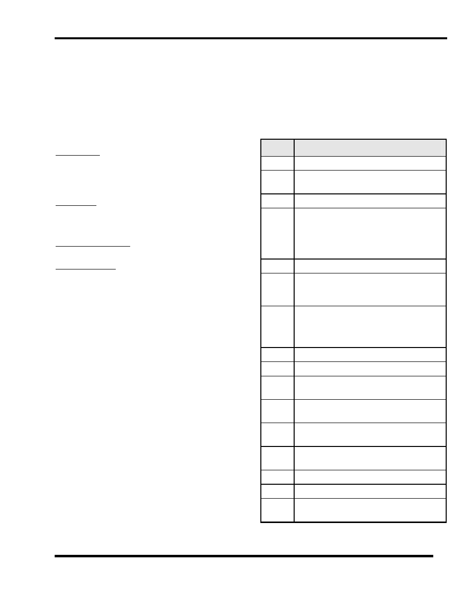
8.3.5 DIAGNOSTIC CODES:
Select the
"SET
USER
CODE"
activity, input user number
"9" and press
ENTER
. The display will indicate
"WARNING:
DIAGNOSTIC
MODE"
and will then ask for
the
ENTRY
CODE
. The following are the codes and their
Function:
Code
Function
0000
Clears all warm-up timers.
0002
Disables error filtering and reduces all warm-
up times.
0003
Not used.
0004
Displays critical module electrical
measurements during normal operation. (H2S:
Sensor signal & Heater Power in mW,
Combustible: Sensor signal & Bridge Power
in mW, O2 & CO: Sensor signal.)
0006
Clears printer buffer.
0007
Clear module X: Asks for the module number
and clears that module's information from the
system memory.
0008
Prints a periodic diagnostic report. The
period is selected in the subsequent menu
selection. (1, 5, 10 , 30 minutes, 1, 8, 12, 24
hours.)
0009
Reset of all diagnostic modes
0010
Prints a single diagnostic report
0012
Forces all Analog Outputs (Model 4314-01)
to 4 mA.
0013
Forces all Analog Outputs (Model 4314-01)
to 20 Ma
0020
Force Calibrates one sensor module. Asks for
the module number after the code is input.
0021
Force Calibrates all uncalibrated sensor
modules.
0022
Disables alarm suppression during calibration.
0023
Restores alarm suppression during calibration
0099
Clears all system RAM including
configuration, calibration and history data.