Sentry Industries 5000 User Manual
Page 42
SMC
sierra monitor corporation
Sentry Instruction Manual - Version 6
CONFIGURATION PROCEDURE
Page: 36
In
NORMAL OPERATE
mode Sentry scans all modules in
sequence and displays their current readings. For any
modules which are not correctly initiated and calibrated
the status will be indicated. This scanning sequence is by
module number by type. (Type 1 = H
2
S solid state, Type
2 = Combustible, Type 3 = Oxygen and Type 4 = all
others)
For H2S, Combustible and Toxic modules the upper
(Sensor/Level) display indicates the module number and
the concentration. The lower display shows the gas tag
and the engineering unit.
For Oxygen the upper display indicates the module
number and its deficiency status. The lower display will
read the oxygen concentration (e.g.: 20.9%).
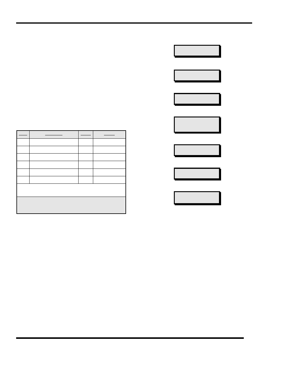
Table 4-1 indicates display conditions for each module
type.
Type
Gas/Status
Upper
Lower
1
H
2
S Normal
00
H2S
PPM%
2
Combustible Normal
00
COMB* %LEL
3
Oxygen Normal
00
OXY
20.9%
3
Oxygen Below Normal
LO
OXY
<20.7%
3
Oxygen Above Normal
HI
OXY
>21.1%
4
Toxic Normal
00
TOXIC*
PPM
* “
COMB
” and “
TOXIC
” gas tags can be modified to any six
character tag using
CHANGE GAS TAGS
.
Table 4-1
Display Conditions
CONTINUOUS
SCAN
is Sentry's default display mode. To
"lock" the display onto one module wait till that module is
displayed and press
ENTER
. While the "lock" is in effect
the arrows can be used to change to other module
numbers. The lock is indicated by "( )" around the top
line of the lower display. To return to
CONTINUOUS
SCAN
press
ENTER
.
Other user selectable display modes are described later in
this manual.
Press the
TEST
button, read the display, then press the
TEST
button again. Repeat until the system returns to the
continuous scan display. The two test conditions which
are displayed are: <
TEST
SYSTEM
> and <
TEST
ALARMS
>.
Neither of these tests were implemented because the
ENTER
key was not pressed.
To implement the tests, press the
TEST
key once; display
will read <
TEST
SYSTEM
>. Press the
ENTER
key. Sentry
will then step through the following series of displays:
Model number, software level, and traceability
descriptors.
MODEL 5000 VERS 6.3
8 CH
951234
Low Alarm Test with relays inactive.
RELAYS PASSIVE
TEST LOW ALARMS
High Alarm Test with relays inactive.
RELAYS PASSIVE
TEST HIGH ALARMS
Trouble Alarm Test with relays inactive.
RELAYS PASSIVE
TEST TROUBLE
ALARM
Full Display Test with all display segments and LED’s on.
X X X X X X X X X X X
X X X X X X X X X X X
Warm-up Time-out.
SYSTEM WARM-UP
PLEASE WAIT 5:00
Return to normal scan.
COMB
%LEL
MODULE TAG
Press the
TEST
key twice and the display will read
TEST
ALARMS
. Press the
ENTER
key and Sentry will execute
LOW
,
HIGH
&
TROUBLE
alarms and then return to the
operate mode. During this test the respective alarm relays
will throw. The user code described later in this manual
can be used to protect against unauthorized activation of
the alarm relays.
Read the Sentry menu, Table 4-2 to find the
TEST
key. It
should now be easy to understand that each step in the
menu can be implemented by using the enter key or
bypassed by continuing to press the activity key. This
process is further described in the flowcharts. Figure 4-3
through Figure 4-7.