Sentry Industries 5000 User Manual
Page 56
SMC
sierra monitor corporation
Sentry Instruction Manual - Version 6
CALIBRATION
Page: 50
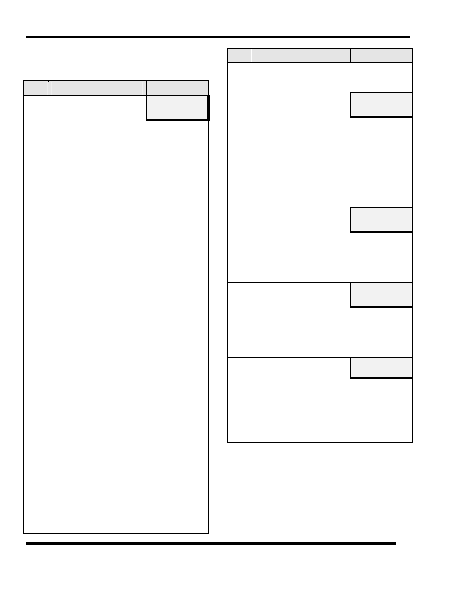
5.3.1.2 LOCAL CALIBRATION
Proceed with the following steps to perform Local
Calibration
Step
Activity
Display
1
Apply
ZERO
and
SPAN
gas to
each sensor.
APPLY
0 & 50%
LEL
1 2 3 4 5 6 7 8
Apply zero and span calibration gas to each
sensor for which calibration is required. (Sensors
which are not exposed will be reported as "Not
Calibrated" and will retain their prior calibration
status).
The calibration gas must be applied via the
magnetic delivery head supplied with the Sentry
system.
1. Remove the rainshield (where applicable).
2. Using the apparatus in Section XXX, thread
the calibration head into the sensor assembly.
At this time the controller top display will
lock onto this module number.
If the ambient environment is one which has been
determined to be clean at the time of
calibration, leave the magnetic head in place
for 30 seconds and then remove. If the
ambient environment is potentially
contaminated, bleed clean air through the
calibration head for two minutes at 100
cc/min and then remove the air and the
calibration head.
3. Wait thirty seconds after the magnet is
removed. During this period the controller
will stop displaying the module number and
will show dashes "- -" on the upper display.
4. Thread the calibration head into the sensor
assembly a second time. The controller will
again lock onto the number for that module
but will add a period immediately following
the number.
Bleed calibration span gas through the
magnetic head at 100 cc (or as required for
permeation tube calibrator). The controller
will display the concentration which would
be determined based on the prior calibration
of the module
5.
Remove the gas and the calibration head,
replace the rainshield and repeat the process
for the next module. As each sensor is
correctly exposed to calibration gas the
respective module number will disappear
Step
Activity
Display
from the display making it possible, at any
time, to read which modules have not been
exposed to calibration gas.
2
Gas application complete - no
errors
CALIB COMPLETE
PLEASE WAIT
3:00
When all modules have received calibration gas
press
ENTER
to indicate completion of the span
process. (Required only if module numbers
remain on the display)
Press
ENTER
again. (Required only if error
messages appear.) If all modules have been
successfully calibrated the controller will begin
the three minute time delay before placing sensor
modules back on line.
3
Error Conditions
- Low Sensitivity
LOW SENSITIVITY
1 2 3 4 5 6 7 8
If any sensors failed to respond correctly to the
calibration gas the low sensitivity message will
identify those sensor module numbers. Note the
number and plan corrective action as described in
Section 7.
4
Error Conditions
- Not Calibrated
NOT CALIBRATED
1 2 3 4 5 6 7 8
Press
ENTER
again. Modules which were not
attempted, and any modules which were displayed
as "LOW SENSITIVITY", will be displayed as
"NOT CALIBRATED". Press ENTER to
acknowledge Press
ENTER
to acknowledge
5
Return to Operate Mode
PRESS ENTER TO
OPERATE MODE
When the time delay is complete the display will
read
PRESS
ENTER
TO OPERATE
MODE
Press
ENTER
and the procedure is complete. Repeat the
process as necessary to recalibrate modules or to
calibrate other gases.
Remove all calibration apparatus from sensors.