Sentry Industries 5000 User Manual
Page 84
SMC
sierra monitor corporation
Sentry Instruction Manual - Version 6
SERVICE
Page: 78
7.9 TOXIC GAS SENSOR MODULE
7.9.1 DESCRIPTION
Toxic Gas Sensor Modules include the following
models and default ranges:
5100-06
Chlorine -10 PPM
5100-07
Hydrogen - 2000 PPM
5100-12
Nitrogen Dioxide - 20 PPM
5100-13
Carbon Monoxide, High Range -
1,000 PPM
5100-10
Sulfur Dioxide - 100 PPM
5100-16
Carbon Monoxide, H2 Tolerant -
2,000 PPM
5100-19
Nitric Oxide - 20 PPM
5100-21
Hydrogen Chloride - 20 PPM
5100-22
Hydrogen Cyanide - 20 PPM
5100-27
Ethylene Oxide - 20 PPM
The Toxic Sensor Module includes a sensor
assembly and electronic assembly installed in an
explosion proof housing.
The sensor assembly includes a reuseable housing
and disposable electrochemical sensor. The
assembly screws into one hub of the sensor
module enclosure and plugs into the bottom
electronics card via a six pin connector.
Cabling from the controller connects to a three pin spring
loaded terminal strip on the electronics assembly.
7.9.2 TROUBLE ANALYSIS
Electrical adjustment, or replacement of the sensor will be
necessary under the following conditions:
•
Controller displays the following error messages
SENSOR FAILURE
LOW SENSITIVITY
•
False readings or alarms are received due to
sensor inaccuracy.
Warning: During sensor adjustments the concentration
reading on the controller will be inaccurate and alarm
level concentrations may be displayed. If false activation
of the alarm relays will cause a problem disconnect the
relay wiring prior to adjustment or turn the module off
using the "Change Module" mode.
NOTE
Although all the necessary data can be collected with a
voltmeter at the sensor module, some helpful
information can be displayed on the controller or
printed. See diagnostic codes 0004 and 0008 in
Appendix C.
7.9.3 ADJUSTMENT PROCEDURE
Prior to reading voltages and making adjustments perform
a visual inspection to confirm that there are no physical
problems such as water in the electronics enclosure,
wiring damage or corrosion.
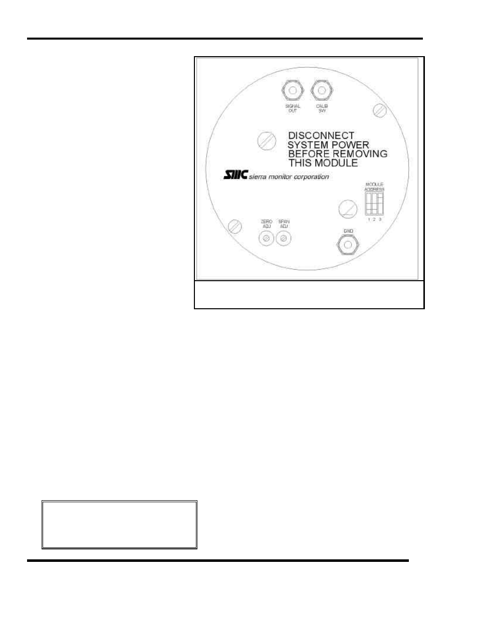
Use Figure 7-11 to locate test points during the following
procedures.
7.9.3.1 SIGNAL ADJUSTMENT
It is unlikely that any electrical adjustment will be
required except when a new sensor is installed.
To make the electrical adjustment connect a voltmeter to
SIGNAL OUT
(pos) and
GND
(ground) and use
SPAN ADJ
potentiometer to adjust the voltage based on the
following:
•
1% of full scale = 0.02 VDC.
•
100% of full scale = 2.00 VDC.
7.9.3.2 SENSOR REPLACEMENT
The toxic gas sensor should be replaced when it can no
longer be calibrated correctly. Generally this is every
twenty four to thirty months.
Figure 7-11
Cover Plate - Toxic Gas Module