Auto switches connection and example, Before operation, Reed switch 2-wire – SMC Networks Reed Switch Solid State Switches User Manual
Page 6: Wire
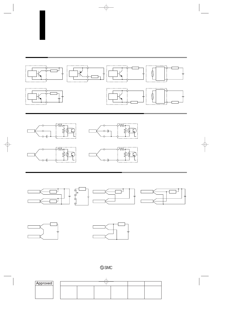
Before Operation
Auto Switches Connection and Example
Basic Wiring
Example of Connection with PLC (Programmable Logic Controller)
Example of AND (Series) and OR (Parallel) Connection
Solid state 3-wire, NPN
Solid state 2-wire
Solid state 3-wire, PNP
Main
curcuit
of switch
Brown
Black
Blue
Brown
Black
Blue
Brown
Blue
Brown
Blue
Reed switch 2-wire
Indicator
protection
circuit,
etc.
Brown
Blue
~
~
Brown
Blue
Indicator
protection
circuit,
etc.
• Sink input specifications
3-wire, NPN
• Source input specifications
3-wire, PNP
2-wire
Switch
Input
Black
COM
Brown
Blue
2-wire
Switch
Input
Black
PLC internal circuit
COM
Brown
Blue
PLC internal circuit
PLC internal circuit
Switch
Input
Blue
COM
Brown
PLC internal circuit
Switch
Input
Blue
COM
Brown
• 3-wire
OR connection for NPN output
2-wire with 2-switch AND connection
2-wire with 2-switch OR connection
Load voltage at ON = Power supply voltage – Residual voltage x 2 pcs.
= 24 V – 4 V x 2 pcs.
= 16 V
Example: Power supply is 24 VDC
Internal voltage drop in switch is 4 V.
Load voltage at OFF = Leakage current x 2 pcs. x Load impedance
= 1 mA x 2 pcs. x 3 kΩ
= 6 V
Example: Load impedance is 3 kΩ.
Leakage current from switch is 1 mA.
Switch 2
Switch 1
Load
Brown
Black
Blue
Brown
Black
Blue
Switch 1
Brown
Switch 2
Black
Blue
Relay
Relay
Brown
Black
Blue
Load
Relay
contact
Switch 1
Switch 2
Brown
Blue
Brown
Blue
Load
Switch 1
Switch 2
Brown
Blue
Brown
Blue
Load
AND connection for NPN output
(Using relays)
• 2-wire
Switch 1
Brown
Switch 2
Black
Blue
Load
Brown
Black
Blue
AND connection for NPN output
(Performed with switches only)
The indicator lights will light up when
both switches are turned ON.
When two switches are
connected in series, a load
may malfunction because
the load voltage will decline
when in the ON state.
The indicator lights will light
up when both of the
switches are in the ON
state.
(Solid state switch)
When two switches are
connected in parallel,
malfunction may occur
because the load voltage
will increase when in the
OFF state.
(Reed switch)
Because there is no
current leakage, the load
voltage will not increase
when turned OFF.
However, depending on
the number of switches in
the ON state, the
indicator lights may
sometimes grow dim or
not light up, due to the
dispersion and reduction
of the current flowing to
the switches.
Brown
Black
Blue
Main
curcuit
of switch
Main
curcuit
of switch
Main
curcuit
of switch
Main
curcuit
of switch
Connect according to the applicable PLC
input specifications, as the connection
method will vary depending on the PLC
input specifications.
(Power supply for switch and load are separate)
Load
Load
Load
Load
Load
Load
Load
12-13-6
1st
12_13_D-.qxd 04.7.6 18:01 Page 13-6
6