D-f9nw(v)/d-f9pw(v)/d-f9bw(v), Auto switch specifications, Weight – SMC Networks Reed Switch Solid State Switches User Manual
Page 20: Dimensions, Grommet, D-f9 w, d-f9 wv (with indicator light), D-f9 २ wv d-f9 २ w indicator light/display method
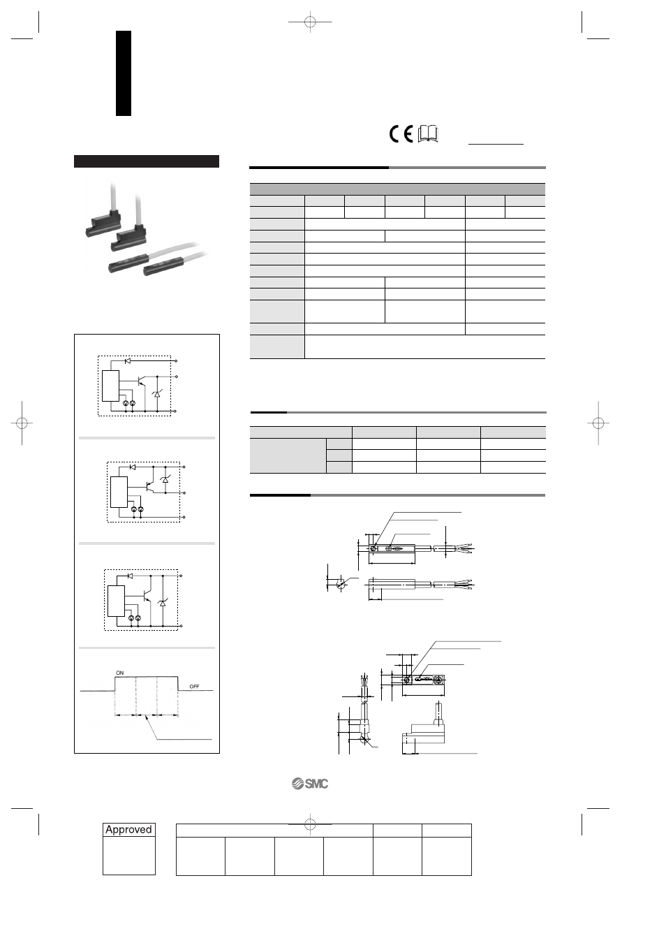
Auto Switch Internal Circuit
D-F9NW, D-F9NWV
D-F9BW, D-F9BWV
D-F9PW, D-F9PWV
Grommet
D-F9
W, D-F9WV (With indicator light)
Auto switch model
Electrical entry direction
Wiring type
Output type
Applicable load
Power supply voltage
Current consumption
Load voltage
Load current
Internal voltage drop
Leakage current
Indicator light
D-F9NW
In-line
D-F9NWV
Perpendicular
D-F9PW
In-line
D-F9PWV
Perpendicular
D-F9BW
In-line
D-F9BWV
Perpendicular
3-wire
IC circuit, Relay, PLC
5, 12, 24 VDC (4.5 to 28 V)
10 mA or less
100 µA or less at 24 VDC
NPN
28 VDC or less
40 mA or less
2-wire
—
24 VDC Relay, PLC
—
—
24 VDC (10 to 28 VDC)
5 to 40 mA
4 V or less
0.8 mA or less
—
80 mA or less
0.8 V or less
PNP
Operating position······Red LED lights when ON.
Optimum operating position······Green LED lights when ON.
1.5 V or less
(0.8 V or less
at 10 mA load current)
Mounting screw M2.5 x 4
l
Slotted set screw
2
2.8
22
ø2.7
Indicator light
2.6
4
Most sensitive position
6
Mounting screw M2.5 x 4
l
Slotted set screw
Indicator light
4.3
2
3.8
3.1
6.2
4
ø2.7
Most sensitive position
6
4.6
2.8
20
D-F9
२WV
D-F9
२W
Indicator light/Display method
Auto switch model
0.5
3
5
D-F9NW(V)
7
34
56
D-F9PW(V)
7
34
56
D-F9BW(V)
7
32
52
Lead wire length
(m)
Auto Switch Specifications
PLC: Abbreviation of Programmable Logic Controller
• Lead wire — Oil resistant vinyl heavy-duty cord: ø2.7, 3 cores (Brown, Black, Blue), 0.15 mm
2
2 cores (Brown, Blue) 0.18 mm
2
, 0.5 m
Note 1) Regarding the common specifications of the solid state switches, refer to page 12-13-5.
Note 2) Regarding the lead wire length, refer to page 12-13-5.
Weight
(g)
Dimensions
Operating range
Indication
Green
Red
Red
Optimum operating position
2-color Indication Type Solid State Switch
Direct Mounting Style
D-F9NW(V)/D-F9PW(V)/D-F9BW(V)
Main circuit
of switch
Main circuit
of switch
Main circuit
of switch
OUT
Black
DC (
+
)
Brown
DC (
–
)
Blue
OUT
Black
DC (
+
)
Brown
DC (
–
)
Blue
OUT (
+
)
Brown
OUT (–)
Blue
For details about certified products
conforming to international standards,
visit us at www.smcworld.com.
12-13-20
1st
12_13_D-.qxd 04.7.6 18:02 Page 13-20
20